COMe Ref. Carrier-i T6 TMI - User Guide Rev. 1.4
// 25
2.3.
System Interfaces
2.3.1.
PCI Express Interfaces
The COMe Ref. Carrier-i T6 TMIP provides three general-purpose PCI Express (PCIe) lanes:
PCIe#0 for the Mini PCIe half-size card slot, J24, connected to the SIM card socket, J35
PCIe#1 for Mini PCIe full-size card slot, J21, muxed with SATA#1 (mSATA), connected to the SIM card socket, J35.
Mini PCIe may be enabled via the onboard DIP switch SW1.
PCIe#2 for onboard Gigabit Ethernet Controller, U29
2.3.2.
SATA Interfaces
The COMe Ref. Carrier-i T6 TMIP supports up to four SATA 6 Gb/s interfaces:
SATA#0 via the 22-pin SATA plug connector, J5, through the redriver ICs, U2 and U3
SATA#1 for the mSATA socket / Mini PCIe full-size card slot, J21, through the redriver ICs, U10 and U11, muxed with
PCIe#1 (Mini PCIe). mSATA may be enabled via the onboard DIP switch, SW1.
SATA#2 through the redriver ICs, U41 and U42, muxed with PEG#0 for the M.2 interface, J34
SATA#3 via the 22-pin SATA receptacle connector, J33, through the redriver ICs, U6 and U8, for the SATA 2.5” HDD
mounting.
2.3.3.
M.2 Interface
The COMe Ref. Carrier-i T6 TMIP provides an M.2 socket, J34, via PEG#[0-3] and SATA#2 (muxed with PEG#0),
which supports 3M key pinning and 2242, 2260 and 2280 M.2 modules
2.3.4.
Gigabit Ethernet Interfaces
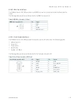
The COMe Ref. Carrier-i T6 TMIP provides up to two Gigabit Ethernet interfaces via two single RJ45 connectors:
GBE#0 on RJ45 Ethernet connector, J18, directly via the COMe basic / compact Type 6 module
GBE#1 on RJ45 Ethernet connector, J20, via the onboard Intel® Ethernet Controller I210-IT, U29 (on PCIe#2)
The Ethernet connector LEDs have the following states:
LINK (green): Ethernet Link
ACT (green): 1000BASE-T Ethernet Speed
ACT (yellow): 100BASE-TX Ethernet Speed ACT (off) + LINK (on): 10BASE-T Ethernet Speed
2.3.5.
USB 2.0 Interfaces
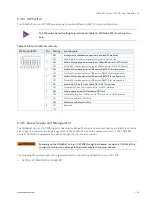
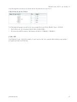
The COMe Ref. Carrier-i T6 TMIP supports eight high-speed USB 2.0 interfaces used as host:
USB#[0;1] are used for USB 3.0/2.0 double-stack connector, J11.
5V standby power for wake events may be enabled and disabled via the onboard DIP switch, SW1.
USB#[2;3] are used for USB 3.0/2.0 pin header, J7
USB#[4;5] are routed to the USB 2.0 double-stack connector, J10.
5V Standby Power for wake events may be enabled or disabled via the onboard DIP switch, SW1.


