COMe Ref. Carrier-i T6 TMI - User Guide Rev. 1.4
// 30
2.3.14.
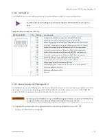
DIP Switch
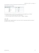
The COMe Ref. Carrier-i T6 TMIP provides one 8-position DIP switch, SW1, for board configuration.
The DIP switch default settings are indicated in Table 16: DIP Switch SW1 Functionality in
bold.
Table 16: DIP Switch SW1 Functionality
DIP Switch (SW1)
Pin
Setting
Functionality
1
ON
Disable rapid shutdown support for Kontron RXT modules
OFF
Enable rapid shutdown support for Kontron RXT modules
2
ON
Enable 5V standby power supply on COMe module for ATX (S-States)
OFF
Disable 5V standby power supply on COMe module for ATX (S-States)
3
ON
Enable 5V standby power to USB ports USB#[4;5] for wake events
OFF
Disable 5V standby power to USB ports USB#[4;5] for wake events
4
ON
Enable 5V standby power to USB ports USB#[0;1] for wake events
OFF
Disable 5V standby power to USB ports USB#[0;1] for wake events
5
ON
Enable mSATA on full-size Mini PCIe / mSATA interface
OFF
Disable mSATA on full-size MiniPCIe / mSATA interface
6
ON
Enable booting from COMe module SPI Flash
OFF
Disable booting from COMe module SPI Flash-Carrier BIOS enabled
7
ON
Wireless disable for Mini PCIe
OFF
Wireless enable for Mini PCIe
8
ON
Reserved
OFF
2.3.15.
Power Supply and Management
The COMe Ref. Carrier-i T6 TMIP supports fixed input voltage (12V only) as a standard feature via the DC jack, J6.and
also supports a wide input voltage range (8.5V - 30V) by default via a wired power connector, J1. The COMe Ref.
Carrier-i T6 TMIP can be powered up either through the J1 or the J6 connector.
Powering up the COMe Ref. Carrier-i T6 TMIP through both power connectors (J1 & J6) at the
same time may result in damage to the power supply unit/power adapter.
The following 12V power supply unit is recommended for use with the COMe Ref. Carrier-i T6 TMIP:
DELTA ELECTRONICS. MDS-150AAS12B


