Functional Description
CP6000
Page 2 - 22
© 2005 Kontron Modular Computers GmbH
ID 27942, Rev. 05
2794
2.05.UG.VC.051020/17275
8
P R E L I M I N A R Y
2.3.9
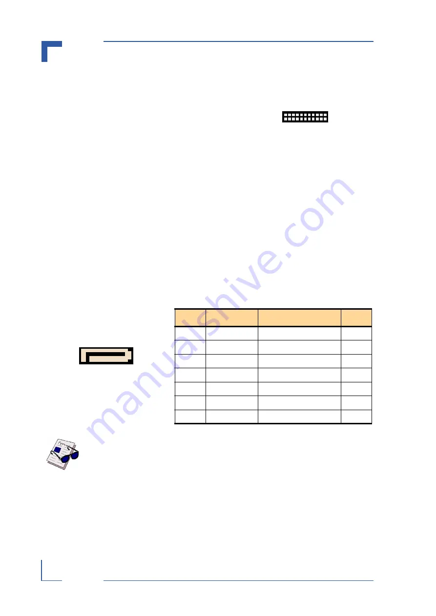
Extension Connector J12
The I/O extension connector provides cost-effective,
flexible configuration options. To provide flexible con-
figuration of additional low speed PC devices, e.g.
Super I/O, IPMI or CAN controller, the LPC port is
connected to the I/O extension connector. The I/O ex-
tension interface contains all the signals necessary to
connect up to two LPC devices.
2.3.10
Serial ATA Interface
The CP6000 supports the new Serial ATA technology through the SATA interface. The SATA
specification allows for thinner, more flexible cables with lower pin count (only 7 pins, instead
of 40 pins as standard EIDE). The current Serial ATA interface allows up to 150 MB/s data
transfer rate, which is faster than the standard Parallel ATA with 100 MB/s (Ultra ATA/100).
Both ports are available on the CompactPCI rear I/O interface. A standard SATA HDD can be
connected to the CP6000 either via the optional SATA connector, J18, or using the CP6000-
EXT-SATA module connected to the optional SATA extension connectors, J30 and J31.
2.3.11
Serial ATA Connector J18 (Optional)
The CP6000 can be equipped with an optional SATA connector, J18, which is used to connect
standard HDDs and other SATA devices to the CP6000.
2.3.12
2.5" SATA HDD Extension Connectors J30 and J31 (Optional)
The CP6000 can be equipped with two optional 12-pin, female SATA extension connectors,
J30 and J31. These connectors are used to connect an onboard 2.5" Serial ATA HDD to the
CP6000 through the CP6000-EXT-SATA module. For further information on the CP6000-EXT-
SATA module, refer to Appendix B.
Note ...
If the onboard SATA interface will be used, due to the big SATA connector and
the stiffly cable, the CP6000 will have a thickness of 8HP and the 2.5" HDD
cannot be directly mounted on the CP6000. Vice versa, if an onboard 2.5" HDD
is mounted on the CP6000, the SATA connector J18 cannot be used.
Figure 2-9: Extension Con. J12
2
1
21
22
Figure 2-10: SATA Connector J18
7
1
Table 2-18: SATA Connector J18 Pinout
PIN
SIGNAL
FUNCTION
I/O
1
GND
Ground signal
--
2
S
Differential R
I
3
SATA_RX2-
Differential Receive -
I
4
GND
Ground signal
--
5
SATA_TX2-
Differential Transmit -
O
6
S
Differential Tr
O
7
GND
Ground signal
--
Artisan Technology Group - Quality Instrumentation ... Guaranteed | (888) 88-SOURCE | www.artisantg.com


