Functional Description
CP6000
Page 2 - 40
© 2005 Kontron Modular Computers GmbH
ID 27942, Rev. 05
2794
2.05.UG.VC.051020/17275
8
P R E L I M I N A R Y
2.4
Intelligent Platform Management Interface
2.4.1
Technical Background of IPMI
The CP6000 has been designed to support the "Intelligent Platform Management Interface"
(IPMI) subsystem which is another step in providing high availability platforms. Intelligent Plat-
form Management means monitoring the health of the entire system beyond the confines of the
board itself, so that the status of the complete system is available to be used, for example, for
control and intervention purposes. A range of variables is monitored on every board, to provide
information on the system status, e.g. voltages, temperature, powergood signals, reset signals
etc. Additionally, the IPMI Baseboard controller can intervene, regulating the operating status
of the system by controlling fans, shutting down systems and generating alarm signals as and
when fault conditions occur. These fault conditions are simultaneously logged in non-volatile
memory for analysis and for fault recovery. IPMI also defines a protocol (software stack) for ex-
changing the status messages of the board, so that "IPMI ready" boards/systems from different
suppliers can be monitored. In addition, a clear interface (registers, addresses etc.) is defined
for guaranteeing that System-Management software can work with every compliant IPMI hard-
ware.
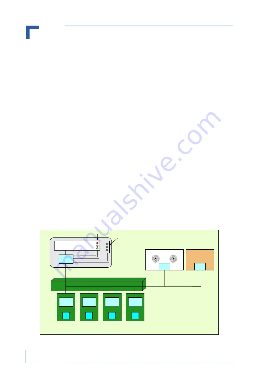
The electrical interconnection between IPMI capable boards is an I²C interface (IPMB). On
CompactPCI systems, this interface is provided on IPMI prepared backplanes and guarantees
the data path between the boards.
The devices which handle the measurements and the protocol stack are microcontrollers
known as Baseboard Management Controller (BMC) and Peripheral Management Controller
(PM). The entire IPMI protocol is controlled by the BMC. On the CP6000, the IPMI controller
can be configured to act as BMC or PM.
The interface between the system controller CPU’s System Management software and the
BaseBoard Management Controller is realized as a keyboard controller style interface (KCS)
which can be found in the board’s I/O space.
Figure 2-15: IPMI Functional Block Diagram
System Chassis
CPU Boards
IPMB
Power Supply
CompactPCI Backplane
Fan Modules
Display Module
Front Panel
Status LEDs
Push Button Inputs
BMC
PM
PM
IPMB
IPMB
CPU
PM
CPU
PM
CPU
PM
CPU
PM
Artisan Technology Group - Quality Instrumentation ... Guaranteed | (888) 88-SOURCE | www.artisantg.com


