Functional Description
CP3002-RC/CP3002-RA
Page 2 - 10
ID 1039-3625, Rev. 1.0
P R E L I M I N A R Y
2.10.5
Gigabit Ethernet Interfaces
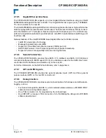
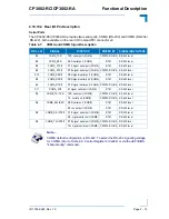
The CP3002-RC/CP3002-RA supports up to four Gigabit Ethernet interfaces using one Intel®
82580EB Quad Gigabit Ethernet controller. Four Gigabit Ethernet copper ports (1000BASE-
TX) are connected to the rear I/O.
The Intel® 82580EB Quad Gigabit Ethernet controller is optimized to deliver high-performance
data throughput with the lowest power consumption. The Ethernet controller is directly connect-
ed to the Intel® Core™ i7 processor chipset using one x4 PCI Express port. The controller sup-
ports auto-negotiation (automatic speed detection), auto MDI-X (automatic wire switching), and
boot from LAN.
Network features of the Intel® 82580EB Quad Gigabit Ethernet controller include:
•
Intel® I/O Acceleration Technology
•
Message Signaled Interrupts (MSI)
•
Support of Virtual Machines Device queues (VMDq) per port
•
IEEE 1588 Precision Time Protocol support and per-packet timestamp
•
Support of various manageability and power saving features
2.10.6
Serial ATA Interface
The CP3002-RC/CP3002-RA provides three SATA I (1.5 Gbit/sec) and SATA II (3.0 Gbit/sec)
compliant interfaces with RAID support (0/1/5). One interface is used for the SATA Flash mod-
ule and two SATA interfaces are available only on the rear I/O.
For further information on the SATA Flash Module, refer to Appendix A.
2.10.7
GPI and GPO Signals
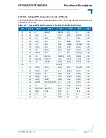
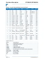
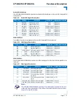
The CP3002-RC/CP3002-RA provides five general purpose inputs (GPI) and three general
purpose outputs (GPO) on the rear I/O connector J2.
2.10.8
Debug Interface
The CP3002-RC/CP3002-RA provides several onboard options for hardware and software de-
bugging, such as:
•
Four bicolor debug LEDs (DLED0..3), which indicate hardware failures, uEFI BIOS POST
codes and user-configurable outputs
•
One JTAG connector, J4, for programming the onboard logic
•
One XDP-SFF, processor JTAG connector, J6, for facilitating the debug and uEFI BIOS
software development

