Installation
CP3002-RC/CP3002-RA
Page 3 - 10
ID 1039-3625, Rev. 1.0
P R E L I M I N A R Y
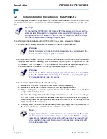
The following sections provide information regarding installation aspects of peripheral devices.
3.7.1
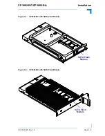
SATA Flash Module Installation
A SATA Flash module may be connected to the CP3002-RC/CP3002-RA via the onboard con-
nector, J3.
This optionally available module must be physically installed on the CP3002-RC/CP3002-RA
prior to installation of the CP3002-RC/CP3002-RA in a system.
During installation it is necessary to ensure that the SATA Flash module is properly seated in
the onboard connector J3, i.e. the pins are aligned correctly and not bent.
3.7.2
Rear I/O Device Installation
For physical installation of rear I/O devices, refer to the documentation provided with the device
itself.
3.8
Software Installation
The installation of the Ethernet and all other onboard peripheral drivers is described in detail in
the relevant Driver Kit files.
Installation of an operating system is a function of the OS software and is not addressed in this
manual. Refer to appropriate OS software documentation for installation.
Note ...
Only qualified SATA Flash modules from Kontron are authorized for use with
the CP3002-RC/CP3002-RA. Failure to comply with the above will void the war-
ranty and may result in damage to the board or the system.
Note ...
Users working with pre-configured operating system installation images for
Plug and Play compliant operating systems, for example Windows® XP, Win-
dows® XP Embedded, must take into consideration that the stepping and revi-
sion ID of the chipset and/or other onboard PCI devices may change. Thus, a
re-configuration of the operating system installation image deployed for a pre-
vious chipset stepping or revision ID is in most cases required. The correspond-
ing operating system will detect new devices according to the Plug and Play
configuration rules.

