Page 2 - 10
Doc.ID: 34938, Rev 1.0
Functional Description
CP342
CUSTOMER SPECIFIC
P R E L I M A R Y
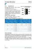
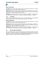
Ethernet LED Status
ACT (green):
This LED monitors network activity. The LED goes temporarily on if network
packets are being sent or received through the RJ45 port.
LINK (green):
This LED monitors network connection. The LED lights up when a valid link (ca-
ble connection) has been established. When this LED remains off, a valid link has not been es-
tablished due to a missing or a faulty cable connection.
SPEED (green):
This LED lights up to indicate a successful 1000BASE-T connection. When
not lit and the ACT-LED is active, the connection is operating at 10Base-T or 100Base-T.
2.3.4
CP342-RIO
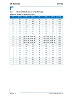
Except for the operational status LEDs, there are no front panel interfaces on the CP342-RIO
board. Refer to the CPCI connector interfacing for pinout of the J2 connector.
Ethernet LED Status
ACT (green):
This LED monitors network activity. The LED goes temporarily on if network
packets are being sent or received through the RJ45 port.
LINK (green):
This LED monitors network connection. The LED lights up when a valid link (ca-
ble connection) has been established. When this LED remains off, a valid link has not been es-
tablished due to a missing or a faulty cable connection.
SPEED (green):
This LED lights up to indicate a successful 1000BASE-T connection. When
not lit and the ACT-LED is active, the connection is operating at 10Base-T or 100Base-T.
2.4
Remote Boot Operation
All of the CP342 versions come with a PLCC32 socket for adding a Boot Flash device. This
Flash device is optional. If installed, it provides additional memory space which can be ad-
dressed from the CPU board’s firmware. Through appropriate Boot Flash code, e.g. PXE com-
patible, it is possible to perform remote boot operations with the CP342.

