background image


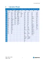
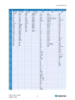
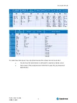
3 Connector Pinout


Kontron User's Guide  
DIMM-PC ADA7 


3


Connector Pinout 


PC/104-BUS 

PC/104-

POWER 

primary 

IDE 

secondary 

IDE 

FLOPPY 

LPT1 

PIN 

A(X1) 

B(X1) 

C(x2) 

D(x2) 

X3 

X24 

X31 

X15 

X13 


GND 

GND 


IOCHCK# 

GND 

SBHE# 

MEMCS16#

GND

RESET#

RESET#

GND 

STB#

SD7 

RSTDRV 

LA23 

IOCS16#

VCC

GND

GND

NC 

AFD#

SD6 

VCC 

LA22 

IRQ10

CODEPIN

SD7

SD7

GND 

PD0

SD5 

IRQ9 

LA21 

IRQ11

+12V

SD8

SD8

NC 

ERR#

SD4 

-5V 

LA20 

IRQ12

-5V

SD6

SD6

GND 

PD1

SD3 

DRQ2 

LA19 

IRQ15

-12V

SD9

SD9

NC 

INIT#

SD2 

-12V 

LA18 

IRQ14

GND

SD5

SD5

GND 

PD2

SD1 

/0WS 

LA17 

DACK0#

VCC

SD10

SD10

FDCIDX# 

SLIN#

SD0 

+12V 

MEMR# 

DRQ0

SD4

SD4

GND 

PD3

10 

IOCHRDY 

GND 

MEMW# 

DACK5#

SD11

SD11

FDCMTR0# 

GND

11 

AEN 

SMEMW#

SD8 

DRQ5

SD3

SD3

GND 

PD4

12 

SA19 

SMEMR#

SD9 

DACK6#

SD12

SD12

NC 

GND

13 

SA18 

IOW# 

SD10 

DRQ6

SD2

SD2

GND 

PD5

14 

SA17 

IOR# 

SD11 

DACK7#

SD13

SD13

FDCDS0# 

GND

15 

SA16 

DACK3# 

SD12 

DRQ7

SD1

SD1

GND 

PD6

16 

SA15 

DRQ3 

SD13 

VCC 

SD14

SD14

NC 

GND

17 

SA14 

DACK1# 

SD14 

MASTER#

SD0

SD0

GND 

PD7

18 

SA13 

DRQ1 

SD15 

GND 

SD15

SD15

FDCDIR# 

GND

19 

SA12 

REFRESH#

GND 

GND 

GND

GND

GND 

ACK#

20 

SA11 

SYSCLK 


NC

NC

FDCSTEP# 

GND

21 

SA10 

IRQ7 


NC

NC

GND 

BUSY#

22 

SA9 

IRQ6 


GND

GND

FDCWDAT# 

GND

23 

SA8 

IRQ5 


IOW#

/IOW

GND 

PE 

24 

SA7 

IRQ4 


GND

GND

FDCWG# 

GND

25 

SA6 

IRQ3 


IOR#

/IOR

GND 

SLCT#

26 

SA5 

DACK2# 


GND

GND

FDCTRK0# 

VCC

27 

SA4 

T/C 


IOCHRDY

IOCHRDY

GND 


28 

SA3 

BALE 


NC

NC

FDCWPRT# 


29 

SA2 

VCC 


NC

NC

GND 


30 

SA1 

OSC 


GND

GND

FDCRDATA# 


31 

SA0 

GND 


IRQ14

IRQ15

GND 


32 

GND 

GND 


IOCS16#

IOCS16#

FDCHDSEL# 


33 


SA1

SA1

GND 


34 


NC

NC

DSKCHG 


35 


SA0

SA0


36 


SA2

SA2


37 


IDE CS0#

S_IDE CS0#


38 


IDE CS1#

S_IDE CS1#


39 


HDLED#

S_HDLED#


40 


GND

GND


41 


VCC


42 


VCC


43 


GND


44 


NC


Summary of Contents for DIMM-PC ADA7

Page 1: ... Kontron User s Guide DIMM PC ADA7 Document Revision 125 ...

Page 2: ...This page intentionally left blank ...

Page 3: ...of Contents Table of Contents 1 4 User Information 1 1 4 About This Manual 1 2 4 Copyright Notice 1 3 4 Trademarks 1 4 4 Standards 1 5 4 Warranty 1 6 5 Technical Support Kontron User s Guide DIMM PC ADA7 iii ...

Page 4: ...therwise without the express written permission of Kontron Embedded Modules GmbH DIMM PC PISA ETX ETXexpress microETXexpress X board DIMM IO and DIMM BUS are trademarks or registered trademarks of Kontron Embedded Modules GmbH Kontron is trademark or registered trademark of Kontron AG Trademarks The following lists the trademarks of components used in this board IBM XT AT PS 2 and Personal System ...

Page 5: ...able for technical support We are committed to making our product easy to use and will help you use our products in your systems Before contacting Kontron Embedded Modules GmbH technical support please consult our Web site at http www kontron emea com emd for the latest product documentation utilities and drivers If the information does not help solve the problem contact us by telephone or email A...

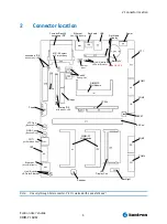
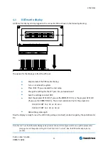
Page 6: ...er JIPA Display Con DIMM PC I O Modules POTI for Dot Matrix Disp CRT Ethernet from I O Module Link Activity LEDs for Ethernet GND Con Banana Plug VCC Con Banana Plug Power Port 80 Debug Out Backlight Floppy primary IDE with activity LED secondary IDE with activity LED MS SL select for CompactFlash Dot Matrix Display Link Activity LEDs for Ethernet Feature Ethernet input Note On every through hole ...

Page 7: ...D4 12 SA19 SMEMR SD9 DACK6 SD12 SD12 NC GND 13 SA18 IOW SD10 DRQ6 SD2 SD2 GND PD5 14 SA17 IOR SD11 DACK7 SD13 SD13 FDCDS0 GND 15 SA16 DACK3 SD12 DRQ7 SD1 SD1 GND PD6 16 SA15 DRQ3 SD13 VCC SD14 SD14 NC GND 17 SA14 DACK1 SD14 MASTER SD0 SD0 GND PD7 18 SA13 DRQ1 SD15 GND SD15 SD15 FDCDIR GND 19 SA12 REFRESH GND GND GND GND GND ACK 20 SA11 SYSCLK NC NC FDCSTEP GND 21 SA10 IRQ7 NC NC GND BUSY 22 SA9 IR...

Page 8: ... SD13 VCC P3 PD1 A GND 17 SA14 DACK1 SD14 MASTER P10 PD2 A GND 18 SA13 DRQ1 SD15 GND P11 PD2 A SA2 19 SA12 REF P18 PD3 A SA1 20 SA11 SYSCLK P19 PD3 A SA0 21 SA10 IRQ7 P4 PD4 A SD0 22 SA9 IRQ6 P5 PD4 A SD1 23 SA8 IRQ5 P6 PD5 A SD2 24 SA7 IRQ4 P7 PD5 A IOCS16 25 SA6 IRQ3 P12 PD6 A GND 26 SA5 DACK2 P13 PD6 A GND 27 SA4 TC P14 PD7 A SD11 28 SA3 BALE P15 PD7 A SD12 29 SA2 VCC P20 VCC 100 OHM SD13 30 SA...

Page 9: ...10 SHLDGND SHLDGN SHLDGN SHLDG CRT MONITOR Backlight LCD Power Feature Connector PIN X11 X28 X18 X16 0 1 RED VCC VCC HDLED 2 GREEN SW BACK GND VCC 3 BLUE 12V I2DAT 4 NC GND VCC 5 GND GND I2CLK 6 GND NC GND 7 GND BACK SRC PGOOD 8 GND DA O0 GND 9 NC NC prg ChipSelect 10 GND FPBACK external SMI 11 NC reserved 12 NC VCC 13 H SYNC reserved 14 V SYNC reserved 15 NC reserved 16 SHLDGND reserved 17 reserv...

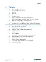
Page 10: ... 2 54mm CompactFlash socket on secondary IDE channel Master Slave selectable by Jumper Note Some CompactFlash Cards may cause problems when used together with other IDE devices 34pos Floppy connector pitch 2 54mm Header for DOT matrix display 7 segment LED displays showing outputs on Debug Port 80 Piezo electronic speaker Reset key battery 3V CR2032 4pos power connector 3pos power connector with s...

Page 11: ...d mode Save the settings and start DOS Start the program D101LCD if you use the DIMM PC D101 or the program D201LCD if you use the DIMM PC D201 The correct commando line for the program is D101LCD COPY 16 2 00 40 00 40 or D201LCD COPY 16 2 00 40 00 40 Reboot the system again Now the display is ready for use The LCD driving voltage contrast can be changed by the potentiometer R3 Note You can t use ...

Page 12: ...l characteristics Supply Voltage 1 5V 12V if LCD backlight is connected Supply current 300mA Note depending on connected CPU and extension boards the current drawn will be higher 1 To protect the external powerlines of peripheral devices the customer has to take care about that the wires have the right diameter to withstand the maximum available current that the enclosure of the peripheral device ...

Page 13: ...Lithiumbatteri Eksplosionsfare ved fejlagtig Håndtering Udskifting må kun ske med batteri af samme fabrikant og type Lever det brugte batteri tilbage til leverand ren Finnish VAROITUS Paristo voi rãjãhtãã jos se on virheellisesti asennettu Vaihda paristo ainoastaan laltevalmistajan suosittelmaan tyyppiln Havita kaytetty paristo valmistajan ohjeiden mukaisesti Spanish Precaución Peligro de explosió...

Page 14: ...raphics missing information added 30 04 99 ADA7K113 DOC 1 3 F Krauss Delete all references to a manual 05 04 02 ADA7K120 DOC 2 0 J Baumgartner All infos according to HW Rev 2 x 24 06 02 ADA7k121 DOC 2 1 J Baumgartner security infos added references to USB removed 11 12 03 ADA7k122 DOC 2 2 D Gunter Changed to Kontron logo Added battery information section 08 02 07 ADA7K123 DOC 2 3 T Schertel Remove...

Reviews: