14 IDE Interfaces
Kontron User's Guide EPIC/CE
43
14.2
CompactFlash Socket
The CompactFlash socket (Connector X13 - 50 pins) for commercial CompactFlashes (Type I) is integrated
on the bottom side of the EPIC/CE board. To find the location of the socket, please see the Appendix E:
Connector Layout chapter.
Because the signals of the socket are connected to the secondary IDE, the socket is not a hot-plug
interface. Turn off power to the system before adding or removing a CompactFlash card.
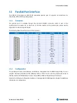
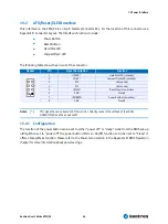
The following table shows the pin-out of the CompactFlash socket.
Pin
Signal Name
Function
Pin
Signal Name
Function
1
GND
Ground
2
D3
Data 3
3
D4
Data 4
4
D5
Data 5
5
D6
Data 6
6
D7
Data 7
7
/CS1
Chip select 1
8
GND
Ground
9
GND
Ground
10
GND
Ground
11
GND
Ground
12
GND
Ground
13
VCC
+5V
14
GND
Ground
15
GND
Ground
16
GND
Ground
17
GND
Ground
18
SA2
Addr. 2
19
SA1
Addr. 1
20
SA0
Addr. 0
21
D0
Data 0
22
D1
Data 1
23
D2
Data 2
24
IOCS16
16 bit CS
25
GND
Ground
26
GND
Ground
27
D11
Data 11
28
D12
Data 12
29
D13
Data 13
30
D14
Data 14
31
D15
Data 15
32
/CS3
Chip select 3
33
GND
Ground
34
/IOR
I/O read
35
/IOW
I/O write
36
VCC
+5V
37
IRQ
Interrupt
38
VCC
+5V
39
GND
Ground
40
NC
Not connected
41
/RESET
Reset
42
IOCHRDY
Ready
43
DRQ
DMA Request
44
DACK
Acknowledge
45
SIDE_ACT
Drive Activity
46
ATADET
ATA detect
47
D8
Data 8
48
D9
Data 9
49
D10
Data 10
50
GND
Ground
14.3
Configuration
The IDE interfaces offer several configuration settings. Refer to the Main Menu, the ACPI Control
submenu, the I/O Device Configuration Submenu, and the Master or Slave Submenu in the Appendix B:
BIOS Operation chapter for additional information on configuration.
Notes
: 1.Use an UDMA flat-ribbon cable (80 lines) to drive UDMA66 or UDMA100 devices.
2. When using a standard ribbon cable (40 lines) with UDMA66 or UDMA100 devices, disable the Ultra DMA
Mode in the BIOS Setup Utility.
Summary of Contents for EPIC/CE
Page 1: ...Kontron User s Guide EPIC CE Document Revision 1 14...
Page 2: ...This page intentionally left blank...
Page 88: ...25 Appendix C Block Diagram Kontron User s Guide EPIC CE 88 25 Appendix C Block Diagram...
Page 93: ...27 Appendix E Connector Layout Kontron User s Guide EPIC CE 93 27 2 Bottom Side...


