background image


24 Appendix B: BIOS Operation


Kontron User's Guide EPIC/CE 

67


24


Appendix B: BIOS Operation 

The EPIC/CE comes with Phoenix BIOS 4.0, Release 6.1, which is located in the onboard Flash EEPROM in 
compressed from. The device has an 8-bit access. The shadow RAM feature offers faster access (16 bit). 
You can update the BIOS using a Flash utility. For complete Phoenix BIOS 4.0 information, visit the 
Phoenix Technologies Web site. 

24.1


Determining the BIOS Version 

To determine the BIOS version of the EPIC/CE, immediately press the <

Pause/Break

> key on your 

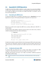
keyboard as soon as you see the following text display in the upper left corner of your screen: 

 
PhoenixBIOS 4.0 Release 6.1 
Copyright 1985-2003 Phoenix Technology Ltd. 

  All 

Rights 

Reserved 


Kontron(R) BIOS Version <E815R111> 


Copyright 2002-2005 Kontron Embedded Modules GmbH 


Whenever you contact technical support about BIOS issues, providing a BIOS version <E815R???> is 
especially helpful. 

The system BIOS provides additional information about the board’s serial number, CPU, and memory 
information by displaying information similar to the following: 

S/N: 

EPA010002


CPU = Mobile Intel(R) Celeron(TM) CPU 733MHz 
254M System RAM Passed 
256K Cache SRAM Passed 
System BIOS shadowed 
Video BIOS shadowed 
 
UMB upper limit segment address: E4D4 


The board’s serial number has valuable information for technical support. EPIC/CE serial numbers always 
start with EP and are followed by a character and six digits. The first three positions represent the lot 
number (here A01), and the last four digits are the number of the board in that lot (here board number 
2). 

24.2


Configuring the System BIOS 

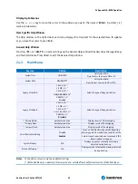
The Phoenix BIOS setup utility allows you to change system behavior by modifying the BIOS 
configuration. Setup-utility menus allow you to make changes and turn features on or off. 

BIOS setup menus represent those found in most models of the EPIC/CE

.

 The BIOS setup utility for 

specific models can differ slightly. 

Note: 

Selecting incorrect values can cause system boot failure. Load setup-default values to recover by pressing 
<

F9

>. 

Summary of Contents for EPIC/CE

Page 1: ...Kontron User s Guide EPIC CE Document Revision 1 14...

Page 2: ...This page intentionally left blank...

Page 3: ...15 4 2 1 PC 104 Bus Connector ISA part 15 4 2 2 PC 104 Plus Bus Connector PCI part 15 4 2 3 Dimensions 15 4 2 4 Height on Top 15 4 2 5 Height on Bottom 15 4 2 6 Weight 15 4 3 Electrical Specification...

Page 4: ...USB Interfaces 29 9 1 Front Connectors USB 0 to USB 3 29 9 2 Internal Connectors USB 4 and USB 5 29 9 2 1 Limitations of USB Ports 4 and 5 30 9 3 Configuration 30 10 Ethernet Interfaces 31 10 1 First...

Page 5: ...3 14 3 Configuration 43 15 Floppy Interface 44 15 1 Connector 44 15 1 1 Connector Diagram 45 15 2 Configuration 45 16 Sound Interface 46 16 1 Connectors 46 16 1 1 Jack Connector 46 16 1 2 Line In Rear...

Page 6: ...2 ACPI Thermal Management 59 22 1 3 Processor Clock Throttling 60 22 2 I O APIC vs 8259 PIC Interrupt mode 60 22 3 Native vs Compatible IDE mode 61 22 3 1 Compatible IDE Mode 61 22 3 2 Native Mode 61...

Page 7: ...ol Submenu 81 24 6 3 Thermal Management Submenu 81 24 7 Boot Menu and Utilities 82 24 7 1 MultiBoot XP 82 24 7 2 Boot First Function 83 24 8 Exit Menu 84 24 9 Kontron BIOS Extensions 84 24 9 1 JIDA BI...

Page 8: ...endix F PC Architecture Information 99 28 1 Buses 99 28 1 1 ISA Standard PS 2 Connectors 99 28 1 2 PC 104 PCI 99 28 2 General PC Architecture 99 28 3 Ports 100 28 3 1 RS 232 Serial 100 28 3 2 ATA 100...

Page 9: ...the express written permission of Kontron Embedded Modules GmbH DIMM PC PISA ETX ETXexpress microETXexpress X board DIMM IO and DIMM BUS are trademarks or registered trademarks of Kontron Embedded Mo...

Page 10: ...e for technical support We are committed to making our product easy to use and will help you use our products in your systems Before contacting Kontron Embedded Modules GmbH technical support please c...

Page 11: ...of the same chassis over the whole product line and maximize design reuse EPIC modules allow the use of standard notebook SODIMM memory modules and full ATX power supplies An optional 5V only version...

Page 12: ...se to the PS 2 connectors Connect the floppy drive cable to the EPIC s floppy interface Attach the floppy drive to the connector at the opposite end of the cable Connect the power supply to the floppy...

Page 13: ...uper I O Two Winbond W83627HF Cache On die 256KB second level cache Memory One 144 pin SODIMM interface that runs in synchronous 133 133 mode and in pseudo synchronous 133 100 mode with FSB133 3 3V PC...

Page 14: ...LAN 1x Davicom DM9102AE DM9102DE PCI Ethernet Controller Follows the common criteria of the embedded technology market segment Onboard Video Graphics Array VGA Intel 815E Chipset graphics memory cont...

Page 15: ...ck through connector 4 2 2 PC 104 Plus Bus Connector PCI part One 4 x 30 pin 2mm downward connector 4 2 3 Dimensions Length x Width 115mm x 165mm 4 53 x 6 49 4 2 4 Height on Top Maximum 32mm 1 26 Heig...

Page 16: ...e Ripple 100mV peak to peak 0 20MHz 4 3 3 Supply Current typical The EPIC CE is equipped with power saving features Different power consumption tests were executed to give an overview of the electrica...

Page 17: ...placement seulement par le m me ou un type quivalent recommand par le producteur L vacuation des batteries usag es conform ment des indications du fabricant Danish ADVARSEL Lithiumbatteri Eksplosionsf...

Page 18: ...which means that the following results were slightly conservative The MTBF values shown below were for a 40 C office or telecommunications environment Higher temperatures and other environmental stre...

Page 19: ...temperature runs at a maximum of 110 C The processor protects itself from catastrophic overheating by use of an internal thermal sensor at a temperature level of approximately 135 C Operating 0 to 60...

Page 20: ...ntegrated math co processor Support for MMX technology Support for Streaming SIMD Extensions Power Management Features including Quick Start Deep Sleep and Deeper Sleep modes which provide low power d...

Page 21: ...scheme Integrated Graphics Controller 3D Hyper Pipelined Architecture Full 2D H W Acceleration Motion Video Acceleration Mip Maps with Trilinear and Anisotropic Filtering 85MHz Flat Panel Monitor Dig...

Page 22: ...r AC 97 support Integrated IDE controller Ultra ATA 100 66 33 and PIO mode support Two channels for up to 3 devices with independent timing Support of Native Mode register and interrupts Interrupt Con...

Page 23: ...es Four serial ports one RS232 available on EPIC board s front and three ports by internal connectors with one port capable of RS422 RS485 functionality One Multi Mode Parallel Port Floppy Disk Contro...

Page 24: ...128 256 or 512MB The total amount of memory available on the SDRAM module is used for main memory and graphics memory on the EPIC CE The Unified Memory Architecture UMA manages how the system shares m...

Page 25: ...nsion connector Row C and D The corresponding 40 pin female header ISA bus 36 pins has four added ground pins including two on each side of the connector To avoid confusion the first two pins are defi...

Page 26: ...s Warning EPIC CE in 5V only version supply the 3 3V to the PC 104 Plus connector via an onboard DC DC converter The DC DC converter is only capable to supply a maximum of 500mA to 3 3V extension card...

Page 27: ...peripheral devices make sure that the wires have the right diameter to withstand the maximum available current the enclosure of the peripheral device fulfils the fire protecting requirements of IEC E...

Page 28: ...can set the PS 2 mouse to enabled disabled or auto detect from the BIOS Setup If you enable the mouse IRQ12 is used as the interrupt and is no longer available for other devices Please refer to the M...

Page 29: ...und Notes To protect the external power lines of peripheral devices make sure that the wires have the right diameter to withstand the maximum available current the enclosure of the peripheral device f...

Page 30: ...orts For high speed USB 2 0 support of all 6 available ports enable the USB EHCI Host Controller You also can enable or disable the legacy USB support Legacy support is required for a USB keyboard and...

Page 31: ...ll major network operating systems and several real time and embedded operating systems support the interface 10 1 First Ethernet Controller Intel 82562 features include IEEE 802 3 10Base T 100Base TX...

Page 32: ...mode for easy system diagnostic Note The Ethernet interface works according to the common criteria of the embedded technology market segment 10 3 Connectors The 10 100Base T interfaces are standard 8...

Page 33: ...B BIOS Operation chapter for additional information on configuration You can download available drivers from the Kontron Web site For further information read the read me file or contact technical sup...

Page 34: ...Ray Tube CRT interface Low Voltage Differential Signaling LVDS interface or Optional Digital Video Output DVO port 11 2 CRT Connector The CRT Cathode Ray Tube interface is available through the stand...

Page 35: ...Out 0 34 CLKB1 opt Clock Out 1 35 GND Ground 36 NC Not connected 37 NC Not connected 38 PD_NS 39 VSYNCB Vertical Sync 40 HSYNCB Horizontal Sync 41 BLANKB Flicker Blank 42 FLDSTLB 43 NC Not connected...

Page 36: ...logic voltage of low voltage panels are powered by separate voltage regulators The one for the LCD is mounted on the JILI adapter cable 11 6 Connecting a LCD Panel To determine whether your panel disp...

Page 37: ...technical support contact either Kontron or obtain support information and downloadable software updates from Intel 11 9 Available Video Modes The following list shows the video modes supported by the...

Page 38: ...6 103h Graphics 800x600 256 105h Graphics 1024x768 256 109h Text 132x25 16 10Ah Text 132x43 16 10Bh Text 132x50 16 10Ch Text 132x60 16 10Eh Graphics 320x200 64K 110h Graphics 640x480 32K 111h Graphics...

Page 39: ...e the other COM ports are available on internal connectors COM A is available through the standard DSUB9 connector which is part of the multi function Connector X1 on the front COM B to COM D are avai...

Page 40: ...have the right diameter to withstand the maximum available current the enclosure of the peripheral device fulfils the fire protecting requirements of IEC EN 60950 12 3 RS 485 Connector You can use Co...

Page 41: ...TB Strobe Out 2 PD0 Data 0 I O 3 PD1 Data 1 I O 4 PD2 Data 2 I O 5 PD3 Data 3 I O 6 PD4 Data 4 I O 7 PD5 Data 5 I O 8 PD6 Data 6 I O 9 PD7 Data 7 I O 10 ACK Acknowledge In 11 BUSY Busy In 12 PE Paper...

Page 42: ...DE interface please see the Appendix E Connector Layout chapter This interface is designed in 0 1 grid for optimal connectivity to a 3 5 hard drive The following table shows the pin out of the IDE con...

Page 43: ...D Ground 18 SA2 Addr 2 19 SA1 Addr 1 20 SA0 Addr 0 21 D0 Data 0 22 D1 Data 1 23 D2 Data 2 24 IOCS16 16 bit CS 25 GND Ground 26 GND Ground 27 D11 Data 11 28 D12 Data 12 29 D13 Data 13 30 D14 Data 14 31...

Page 44: ...cable KAB FLOPPY MOPS 1 Part Number 96019 0000 00 0 It also is possible to get a slim line 3 5 floppy drive with cable from Kontron FLOPPY MOPS 1 Part Number 96010 0000 00 0 The following table shows...

Page 45: ...Utility You can choose the 3 5 common or 5 25 drive types with densities of 360kB 720kB 1 2MB 1 25MB 1 44MB or 2 88MB Refer to the Main Menu and the Miscellaneous Menu section of the Appendix B BIOS...

Page 46: ...anagement capabilities Embedded 50mW 20ohm OP at front LINE output 6 Channel output for multi channel applications 16 1 Connectors The EPIC CE offers two connectors related to the Sound feature One is...

Page 47: ...Appendix E Connector Layout chapter If using these signals as Line In a CDROM can be connected using a standard CDROM Audio cable The pin out of this connector complies with the standard pin out used...

Page 48: ...cur you can solve some of them by using the latest drivers for the Sound controller Kontron provides you with the latest tested drivers which can differ from newer ones For further technical support c...

Page 49: ...tor Top View Pin GPIO GP0 12csu 1 2 GP14 12t GP1 12csu 3 4 GP15 12t GP2 12cs 5 6 GP16 12t GP3 12cs 7 8 GP17 12t GP4 12cs 9 10 GP18 24t GP5 12cs 11 12 GP19 12t GP6 12cs 13 14 GP20 12t GP7 12csu 15 16 G...

Page 50: ...ship between Super I O and GPIOs GPIO Controller Logical Device Index Register Address Data Register Address GP0 7 Super I O 2 Logical Device 7 4Eh 4Fh GP8 13 Super I O 2 Logical Device 9 4Eh 4Fh GP14...

Page 51: ...on register F2hex Configuration register F1hex is the data register to read from or write to Configuration Register Purpose Explanation Default Value F0hex Direction 0 output 1 input 11111111bin F1hex...

Page 52: ...JMP 2 Wait OUT DX AL Second Write STI Enable Interrupts 17 2 2 32 Bit Operating Systems Kontron Embedded Modules GmbH offers a 32bit API JIDA32 which also includes protected mode functions to read an...

Page 53: ...scription Function 1 Sense Speed Monitoring 2 VCC 5V 3 GND Ground Notes To protect the external power lines of peripheral devices make sure that the wires have the right diameter to withstand the maxi...

Page 54: ...ages are not generated onboard the EPIC CE and need to be supplied too as soon as peripheral devices require these voltages We recommend that you use an ATX power supply with this type of EPIC CE even...

Page 55: ...hich add on PC 104 Plus cards cannot exceed a supply current of 1A 1 5A absolute maximum The following table shows the pin out of the AT connector Header Pin Signal Description Function 1 V5S 5V 2 GND...

Page 56: ...pactFlash LED cathode 3 VCC 5V anode 4 VCC 5V anode 5 RESIN Reset Input low active 6 GND Ground 7 PWRBTN Power Button low active 8 GND Ground Notes This signal has an onboard 470 Ohm resistor Directly...

Page 57: ...imeout is the time the watchdog timer has to be triggered within You can make the initialization settings in the BIOS setup Refer to the Watchdog Settings Submenu in the Appendix B BIOS Operation chap...

Page 58: ...PU core voltage 5V standby voltage Battery voltage CPU temperature with on die diode CPU fan speed planed 21 1 Configuration You can use the Hardware Monitor submenu in the BIOS Setup Utility to obtai...

Page 59: ...ng mode does not require additional hardware software drivers or interrupt handling routines This feature should be used with none ACPI aware operating systems 22 1 2 ACPI Thermal Management ACPI allo...

Page 60: ...2 I O APIC vs 8259 PIC Interrupt mode The I O APIC Advanced Programmable Interrupt Controller handles interrupts differently than the 8259 PIC Enable the I O APIC mode in the BIOS Setup Utility if you...

Page 61: ...ing only one shareable interrupt instead of two non shareable ones native mode controllers significantly decrease the likelihood that a user will install a device that cannot work because no interrupt...

Page 62: ...Sound No Note 1 Note 2 Note 4 6 FDC No Note 1 7 LPT1 No Note 1 8 RTC No 9 SCI Yes Note 3 10 COM4 No Note 1 11 COM3 No Note 1 12 PS 2 Mouse No Note 1 13 FPU No 14 IDE0 No Note 1 15 CompactFlash IDE1 N...

Page 63: ...o 21 PIRQ F No 22 PIRQ G No 23 PIRQ H No Notes 1 If the used for device is disabled in setup the corresponding interrupt is available for other devices 2 Possible setting for LPT1 IRQ7 is the default...

Page 64: ...add on boards also have optional ROMs or use drivers that communicate with their corresponding devices via memory mapped I O such as dual ported RAM These boards have to share the upper memory area wi...

Page 65: ...DE port 2 is disabled or in native IDE mode 0378 037F LPT No Available if LPT is disabled 03BC 03C3 LPT Yes Possible address for LPT 03B0 03DF Graphic Subsystem No Fixed 03E8 03EF COM3 No Available if...

Page 66: ...egrated in Intel chipset 2nd UHCI USB Controller INTD Separate bus integrated in Intel chipset 3rd UHCI USB Controller INTC Separate bus integrated in Intel chipset EHCI USB Controller INTH Separate b...

Page 67: ...helpful The system BIOS provides additional information about the board s serial number CPU and memory information by displaying information similar to the following S N EPA010002 CPU Mobile Intel R C...

Page 68: ...ys to make a selection Legend Bar Use the keys listed in the legend bar on the bottom to make your selections or exit the current menu The table below describes the legend keys and their alternates Ke...

Page 69: ...A 360 Kb 5 1 2 MB 5 720 Kb 3 1 44 1 25 MB 3 2 88 MB 3 Disabled Select the type of floppy disk drive Legacy Diskette B 360 Kb 5 1 2 MB 5 720 Kb 3 1 44 1 25 MB 3 2 88 MB 3 Disabled Select the type of f...

Page 70: ...lculated size of the drive in LBA Multi Sector Transfer Disabled 2 sectors 4 sectors 8 sectors 16 sectors Any selection except Disabled determines the number of sectors transferred per block The stand...

Page 71: ...ption column bold shows default settings 24 4 2 PCI PNP Configuration Submenu Feature Option Description PNP OS installed No Yes If your system has a PnP OS such as Win9x select Yes to let the OS conf...

Page 72: ...te In the Option column bold shows default settings 24 4 4 PCI PNP ISA IRQ Resource Exclusion Submenu Feature Option Description IRQ3 Available Reserved Reserves the specified IRQ for use by legacy IS...

Page 73: ...Uncached Write Through Write Protected Write Back Controls caching of base memory up to 512KB Cache Extended Memory area Uncached Write Through Write Protected Write Back Controls caching of system me...

Page 74: ...Disabled Enabled Enables the Davicom LAN controller Floppy disk controller Disabled Enabled Enable Disable the onboard FDC controller Serial port A B C D Disabled Enabled Auto Disabled turns off the...

Page 75: ...8 Hardware Monitor Submenu This submenu shows the current voltages temperatures and the fan speed of the system Voltage Temperature Fan Explanation VCC 3 3V Voltage 3 3V power plane CPU Core Voltage...

Page 76: ...I3 ID values PAID FPID 0 FFFF default 0 Enter the JILI3 ID Flat Panel Backlight 0 255 default 128 Enter a value to adjust backlight of the LCD Flat Panel Contrast 0 63 default 32 Enter a value to adju...

Page 77: ...post errors cause the system to halt PS 2 Mouse Auto Detect Enabled Disabled Selecting Disabled prevents any installed PS 2 mouse from functioning but frees up IRQ12 Selecting Autodetect frees IRQ12...

Page 78: ...ekly Monthly Displays a message during boot up asking Y N if you backed up the system or scanned for viruses Message returns on each boot until you respond with Y Daily displays the message on the fir...

Page 79: ...u intend to use an operating system supporting the Advanced Configuration and Power Management Interface For logical reasons it is required to use an ATX power supply with the ACPI feature The followi...

Page 80: ...Inactivity period of user input device before the screen is turned off Resume on Modem Ring Off On Enabled wakes system on incoming calls detected by mode RI Resume on Time Off On Enabled wakes the s...

Page 81: ...Native IDE Support Disabled Enabled Enable Native IDE support for WINXP by setting this item The NATA Package will be created if this item is set to Enabled Changing this item will have no effect in...

Page 82: ...neric and flexible enough to boot from any current device You can select your boot device in Setup or you can choose a different device each time you boot by selecting your boot device in the Boot Fir...

Page 83: ...IP Drive USB LS120 USB LS120 Drive PCI BEV Ethernet Controller on the PCI Bus with LAN Boot ROM PCI SCSI SCSI Controller on the PCI Bus with SCSI BIOS ROM 24 7 2 Boot First Function Display the Boot F...

Page 84: ...sion you change your mind about changes you have made and have not yet saved the values to CMOS you can restore the values you saved to CMOS Discard changes Save Changes Saves all the selection withou...

Page 85: ...system BIOS scans the serial ports for an available JRC connection If detected it loads the JRC client BIOS extension into the memory With the JRC client loaded into the first detected free memory loc...

Page 86: ...ZIP into a local directory such as C PHLASH Create a Crisis Recovery Diskette by inserting a blank diskette into Drive A or B and execute WINCRISIS EXE This copies three files onto the diskette File P...

Page 87: ...t block region contains a fail safe recovery routine If the boot block code finds a corrupted BIOS checksum fails it boots into the crisis recovery mode and loads a BIOS image from a crisis diskette s...

Page 88: ...25 Appendix C Block Diagram Kontron User s Guide EPIC CE 88 25 Appendix C Block Diagram...

Page 89: ...26 Appendix D Mechanical Dimensions Kontron User s Guide EPIC CE 89 26 Appendix D Mechanical Dimensions 26 1 Board Dimensions and Mounting Holes 26 1 1 Top View 26 1 2 Front View...

Page 90: ...26 Appendix D Mechanical Dimensions Kontron User s Guide EPIC CE 90 26 2 Connector Locations Pin 1...

Page 91: ...26 Appendix D Mechanical Dimensions Kontron User s Guide EPIC CE 91 26 3 Slot Dimensions 26 3 1 Front and Top View...

Page 92: ...27 Appendix E Connector Layout Kontron User s Guide EPIC CE 92 27 Appendix E Connector Layout 27 1 Top Side Notes The position of Pin 1 is marked with a quadratic pad on the PCB...

Page 93: ...27 Appendix E Connector Layout Kontron User s Guide EPIC CE 93 27 2 Bottom Side...

Page 94: ...For CRT monitor connection Serial Interface Connectors COM A Standard DSUB9 female plug For DSUB9 RS232 connection X1 Parallel Interface LPT Connector Standard DSUB25 male plug For DSUB 25 LPT connect...

Page 95: ...nterfaces Standard PS 2 plugs For PS 2 Mouse and Keyboard X19 Serial Interface Connector COM D 2 5mm 5 pos JST XHP 5 or compatible For RS485 connection X20 X25 USB interface connector 1 25mm 4 pos Mol...

Page 96: ...1 GND PD7 NC PIDE_D4 GND NC 10 VCC ACK MTR0 PIDE_D11 GND GND 11 BUSY NC PIDE_D3 GND NC 12 PE FDIR PIDE_D12 GND DDDA 13 SLCT NC PIDE_D2 VCC HSYNC 14 AFD STEP PIDE_D13 GND VSYNC 15 ERR GND PIDE_D1 GND D...

Page 97: ...NC GP16 5V_SB 7 NC GP3 5V 8 NC GP17 5V 9 GP4 12V 10 GP18 GND 11 GP5 12 GP19 13 GP6 14 GP20 15 GP7 16 GP21 17 GP8 18 GP22 19 GP9 20 GP23 21 GP10 22 GP24 23 GP11 24 GP25 25 GP12 26 GND 27 GP13 28 GND No...

Page 98: ...SD11 DACK7 GND AD16 VCC3 C BE2 15 SA16 DACK3 SD12 DRQ7 AD18 VCC3 AD17 GND 16 SA15 DRQ3 SD13 VCC AD21 AD20 GND AD19 17 SA14 DACK1 SD14 MASTER VCC3 AD23 AD22 VCC3 18 SA13 DRQ1 SD15 GND IS0 AD20 GND IS1...

Page 99: ...n about PC 104 and PC 104 Plus technology You can search for information about the consortium on the Web PCI SIG The PCI SIG provides a forum for its 900 member companies who develop PCI products base...

Page 100: ...n disk drives and host processors It provides a common point of attachment for systems manufacturers and the system You can search for information about the working group on the Web We recommend you a...

Page 101: ...consumption E815M110 20 07 2005 VGG Add 3 3V in PCI mechanical drawings RS485 connector first official release E815M111 01 09 2005 BHO Changed to Kontron style added lots of information E815M112 07 09...

Reviews: