FusionClient – User Guide (Rev. 1.3)
www.kontron.com
// 42
The FC 121 system will be secured into a wall/panel by use of:
two mounting clamps at the top and bottom side
two mounting clamps at the left and right side
4.4.15.
Air Openings on the bottom Side of the Touch Display Unit
The air intake openings (Figure 11, pos. 6) are situated on the bottom side of the touch display unit.
When powering on the FusionClient, make sure that the air intake and exhaust
openings are not obstructed.
4.5.
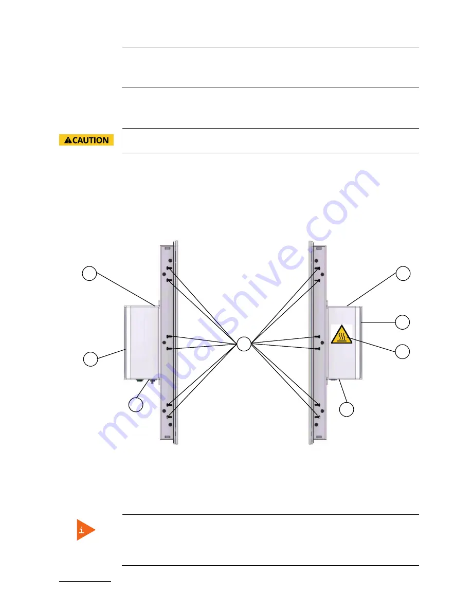
Left and Right Side View
On the left and right side of the system are situated mounting slot for installation of the mounting clamps
with screws.
Figure 19: Left side of the FusionClient shown as FC
215
Figure 20: Right side of the FusionClient shown as
FC 215
Legend for Figure 19 and Figure 20:
1
Mounting slots for installing the
mounting clamps with screws
2
Top side of the computer base
3
Cooling fins of the computer base
4
Interface side (bottom)
5
Warning Label “Hot Surface”
Note for mounting clamps:
The FC 215 and FC 185 system will be secured into a wall/panel by use of:
four mounting clamps at the top and bottom side
three mounting clamps at the left and right side
2
2
3
4
3
4
5
1
Summary of Contents for FusionClient FC 121
Page 1: ...FusionClient Fusion Client User Guide Rev 1 3 Doc ID 1060 3249 ...
Page 2: ...Fusion Client User Guide Rev 1 3 This page has been intentionally left blank ...
Page 7: ...Fusion Client User Guide Rev 1 3 ...
Page 32: ...FusionClient User Guide Rev 1 3 www kontron com 32 ...
Page 46: ...FusionClient User Guide Rev 1 3 www kontron com 46 flammable materials under the device ...
Page 48: ...FusionClient User Guide Rev 1 3 www kontron com 48 ...
Page 58: ...FusionClient User Guide Rev 1 3 www kontron com 58 ...
Page 70: ...FusionClient User Guide Rev 1 3 www kontron com 70 ...


