background image

Component Description

OM6040D

Page 2 - 2

ID: 1038-6516, Rev. 1.0

This page has been intentionally left blank.

Summary of Contents for MicroTCA OM6040D

Page 1: ...If it s embedded it s Kontron User Guide OM6040D MicroTCA Four Slot Double Full size Single Tier Cube Shelf Doc ID 1038 6516 Rev 1 0 July 13 2010...

Page 2: ...purposes Information has been carefully checked and is believed to be accurate however no responsibility is assumed for inaccuracies Kontron and the Kontron logo and all other trademarks or registere...

Page 3: ...Your Safety xi Temperature and High Voltage Safety Instructions xi Special Handling and Unpacking Instructions xi General Instructions on Usage xii Two Year Warranty xiii 1 Introduction 1 3 1 1 Overvi...

Page 4: ...ID 1038 6516 Rev 1 0 3 3 Prerequisites 3 5 3 3 1 Cooling 3 5 3 3 2 Filler Panels 3 5 3 4 Mounting 3 6 3 5 Adding or Replacing OM6040D Components 3 6 3 6 Cooling Air Filter Maintenance 3 6 3 7 AMC Conn...

Page 5: ...OM6040D Preface ID 1038 6516 Rev 1 0 Page v List of Tables 1 1 OM6040D Shelf Specifications 1 5 1 2 Standards 1 7 1 3 Related Publications 1 8 3 1 OM6040D Base Solution Configuration 3 3...

Page 6: ...Preface OM6040D Page vi ID 1038 6516 Rev 1 0 This page has been intentionally left blank...

Page 7: ...M6040D Shelf Front View 2 4 2 2 OM6040D Shelf Back View 2 5 2 3 OM6040D Shelf Bottom View 2 6 2 4 OM6040D Shelf Top View 2 7 2 5 OM6040D Shelf Left Side View Cutaway 2 8 2 6 Backplane Front View 2 9 2...

Page 8: ...Preface OM6040D Page viii ID 1038 6516 Rev 1 0 This page has been intentionally left blank...

Page 9: ...uit product or example shown in this document Kontron reserves the right to change modify or improve this document or the product described herein as seen fit by Kontron without further notice Tradema...

Page 10: ...evice This symbol and title inform that electronic boards and their compo nents are sensitive to static electricity Therefore care must be taken during all handling operations and inspections of this...

Page 11: ...important for the user to be electrically discharged before touching the product with his her hands or tools This is most easily done by touching a metal part of your system housing Warning All operat...

Page 12: ...also to the operational temperature range of the specific board version which must not be exceeded If batteries are present their temperature restrictions must be taken into account In performing all...

Page 13: ...riginal cost of purchase if appropriate In the event of repair refunding or replacement of any part the ownership of the removed or replaced parts reverts to Kontron and the remaining part of the orig...

Page 14: ...Preface OM6040D Page xiv ID 1038 6516 Rev 1 0 This page has been intentionally left blank...

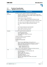
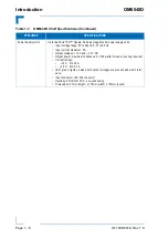
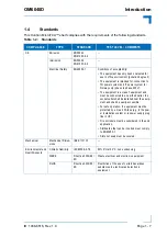
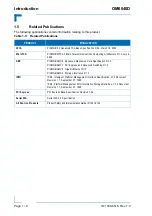
Page 15: ...OM6040D Introduction ID 1038 6516 Rev 1 0 Page 1 1 Introduction Chapter 1 1...

Page 16: ...Introduction OM6040D Page 1 2 ID 1038 6516 Rev 1 0 This page has been intentionally left blank...

Page 17: ...E Fabric interface Integrated cooling fans The OM6040D supports up to four Double Full size AMC Modules with various possible con figurations of AMC CPUs and peripheral devices Up to two pluggable Pow...

Page 18: ...Introduction OM6040D Page 1 4 ID 1038 6516 Rev 1 0 Figure 1 1 OM6040D Shelf Perspective View with Feet and Mounting Brackets Power MCH Slot AMC Fan Bay Slots Supply Units PSUs...

Page 19: ...shelf with PSUs and fans Backplane MicroTCA compliant single tier backplane with Four AMC module connectors One four tongue MCH connector Two pluggable Power Supply Unit connectors Fan connector Inpu...

Page 20: ...ages 12 V and 3 3 V DC Output power maximum continuous 2 x 300 watts forced air cooling required Current ratings 12 V 0 to 25 A 3 3 V 0 to 2 4 A LED green lights up when both output voltages are prese...

Page 21: ...s 1 equipment and must be connected to an earthed outlet the socket outlet shall be installed near the equip ment and shall be easily accessible For safe operation the equipment must be protected by a...

Page 22: ...G AMC 0 Advanced Mezzanine Card Specification R2 0 PICMG AMC 1 PCI Express and Advanced Switching R1 0 PICMG AMC 2 Gigabit Ethernet R1 0 PICMG AMC 3 Storage Interfaces R1 0 IPMI IPMI Intelligent Platf...

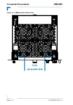
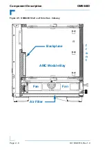
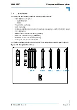
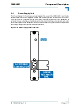
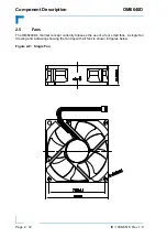
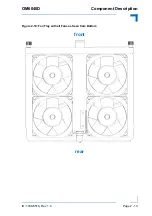
Page 23: ...OM6040D Component Description ID 1038 6516 Rev 1 0 Page 2 1 Component Description Chapter 1 2...

Page 24: ...Component Description OM6040D Page 2 2 ID 1038 6516 Rev 1 0 This page has been intentionally left blank...

Page 25: ...over the system slots The OM6040D is delivered with four feet of which the front two are retractable for placement on a desktop or shelf Mounting brackets are also provided for rack mounting The shelf...

Page 26: ...Component Description OM6040D Page 2 4 ID 1038 6516 Rev 1 0 Figure 2 1 OM6040D Shelf Front View 258 12 240 62 PSU1 Fan Bay AMC Slot 4 AMC Slot 3 MCH PSU2 AMC Slot 2 AMC Slot 1...

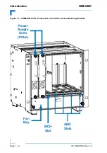
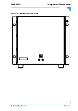
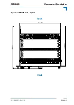
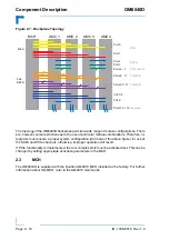
Page 27: ...OM6040D Component Description ID 1038 6516 Rev 1 0 Page 2 5 Figure 2 2 OM6040D Shelf Back View...

Page 28: ...Component Description OM6040D Page 2 6 ID 1038 6516 Rev 1 0 Figure 2 3 OM6040D Shelf Bottom View front retractable feet...

Page 29: ...OM6040D Component Description ID 1038 6516 Rev 1 0 Page 2 7 Figure 2 4 OM6040D Shelf Top View 217 72 230 70 215 00 front back...

Page 30: ...Component Description OM6040D Page 2 8 ID 1038 6516 Rev 1 0 Figure 2 5 OM6040D Shelf Left Side View Cutaway AMC Module Bay f r o n t Fan Fan Air Filter Backplane...

Page 31: ...interfacing Input power distribution and control for payload management and MCH MCMC power Clock distribution IPMI monitor and control interfacing IPMB L Backplane FRU data storage EEPROM MCMC I C mo...

Page 32: ...SATA and PCIe channels otherwise improper operation will result If PCIe functionality is implemented the root complex slots must be activated last This can be changed by setting appropriate activation...

Page 33: ...fix the PSU to the sub rack Input power is supplied via the front panel connector Interfacing to the backplane is achieved via a very high power load Molex connector which interfaces power as well as...

Page 34: ...e 2 12 ID 1038 6516 Rev 1 0 2 5 Fans The OM6040D s thermal concept currently foresees the use of a four small fans A single fan drawing and a drawing showing the fan tray with all fans is shown in fig...

Page 35: ...OM6040D Component Description ID 1038 6516 Rev 1 0 Page 2 13 Figure 2 10 Fan Tray with all Fans as Seen from Bottom front rear...

Page 36: ...Component Description OM6040D Page 2 14 ID 1038 6516 Rev 1 0 This page has been intentionally left blank...

Page 37: ...OM6040D Installation ID 1038 6516 Rev 1 0 Page 3 1 Installation Chapter 1 3...

Page 38: ...Installation OM6040D Page 3 2 ID 1038 6516 Rev 1 0 This page has been intentionally left blank...

Page 39: ...the following Installa tion sections Table 3 1 OM6040D Base Solution Configuration COMPONENT QTY COMPONENT LOCATION DESCRIPTION Subrack 1 Mechanical chassis of OM6040D Backplane 1 Power Supply Unit PS...

Page 40: ...life or health and may cause damage to the OM6040D or other system components including pro cess side signal conditioning equipment ESD Equipment The OM6040D contains electrostatic sensitive devices E...

Page 41: ...n the final application 3 3 2 Filler Panels Operation of the OM6040D requires that all slots be fully occupied or appropriate filler panels must be installed to close any open front area s To accompli...

Page 42: ...f the slot Then install the new PSU fasten the retaining screws and reconnect the main power cable As required apply power again to the system To replace the fan tray first remove main power from the...

Reviews: