
Installation
OM6040D
Page 3 - 6
ID: 1038-6516, Rev. 1.0
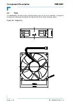
3.4
Mounting
The OM6040D is supplied with fixed mounting brackets for installation in a system cabinet. For
cabinets which are wider than the OM6040D, additional mounting hardware is required which
is not supplied with the OM6040D.
For operation of the OM6040D on a flat surface, desktop or rack shelf, there are no special
mounting fixtures except for the four feet. In this case, for operation the front feet should be
extended to ensure adequate airflow to the OM6040D. Care must also be taken to ensure that
OM6040D cannot fall off of the flat surface.
3.5
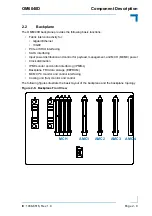
Adding or Replacing OM6040D Components
Solution requirements determine the operational configuration of the OM6040D. Therefore, it
may or will be necessary to add, remove, or reconfigure components. AMC modules are nor-
mally supplied with documentation which provides instructions or guidelines on their installation
or replacement. Please refer to this documentation for further assistance.
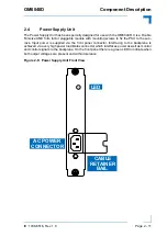
OM6040D specific components and the backplane, are not user replaceable. The Power Sup-
ply Units (PSUs) and the fan tray are, however, user replaceable.
Replacement of the PSU requires that the main power be removed from the system. Therefore,
it is necessary to ensure that the system is properly prepared for powering down. Once the sys-
tem is powered down, remove the power cable to the PSU, unscrew the retaining screws and
slide it out of the slot. Then install the new PSU, fasten the retaining screws, and reconnect the
main power cable. As required, apply power again to the system.
To replace the fan tray, first remove main power from the system. Then unscrew the two Fan
Bay front panel thumbscrews and remove the fan tray. Install the new fan tray, tighten the two
Fan Bay front panel thumbscrews, and reapply main power as required.
3.6
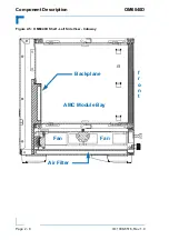
Cooling Air Filter Maintenance
The OM6040D is provided with a cooling air filter which is located underneath the fans at the
bottom of the subrack. To gain access to the air filter, unscrew the two Fan Bay front panel
thumbscrews and remove the fan tray. The air filter has a frame holder which is used to extract
the filter from the chassis. To inspect, clean, or replace the filter, pull it out of the chassis.
Typically the air filter should be inspected every three months. As required, it should be cleaned
or replaced. If the system is operated in a dusty, oily, or otherwise contaminated environment
the filter should be inspected at shorter intervals, eventually once a month.
3.7
AMC Connector Mating Cycles
The OM6040D backplane connectors and the AMC module card-edge connectors are de-
signed to support at least 200 insertion/extraction cycles. As systems used in a laboratory or
development environment may exceed this number of mating cycles over the product life time,
the card-edge connector of each AMC module should be inspected for wear or damage before
insertion or after extraction. If a card-edge connector exhibits excessive wear or damage, the
AMC module must be replaced to preclude improper operation of the system.
Summary of Contents for MicroTCA OM6040D
Page 6: ...Preface OM6040D Page vi ID 1038 6516 Rev 1 0 This page has been intentionally left blank...
Page 8: ...Preface OM6040D Page viii ID 1038 6516 Rev 1 0 This page has been intentionally left blank...
Page 14: ...Preface OM6040D Page xiv ID 1038 6516 Rev 1 0 This page has been intentionally left blank...
Page 15: ...OM6040D Introduction ID 1038 6516 Rev 1 0 Page 1 1 Introduction Chapter 1 1...
Page 16: ...Introduction OM6040D Page 1 2 ID 1038 6516 Rev 1 0 This page has been intentionally left blank...
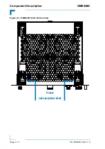
Page 23: ...OM6040D Component Description ID 1038 6516 Rev 1 0 Page 2 1 Component Description Chapter 1 2...
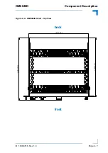
Page 27: ...OM6040D Component Description ID 1038 6516 Rev 1 0 Page 2 5 Figure 2 2 OM6040D Shelf Back View...
Page 37: ...OM6040D Installation ID 1038 6516 Rev 1 0 Page 3 1 Installation Chapter 1 3...
Page 38: ...Installation OM6040D Page 3 2 ID 1038 6516 Rev 1 0 This page has been intentionally left blank...