Chapter 7
Graphics Interface
Kontron User's Guide PC/104-520
16
7.3
Connecting a LCD Panel
To determine whether your panel display is supported, check the Kontron Website for panel lists. We regu-
larly update the list of panels that have been tested with the PC/104-520.
If you use one of those cables supplied by Kontron, configuration is easy:
Check whether you have the correct cable for the panel you plan to use. Inspect the cable for
damages. Disconnect the power from your system.
Check Jumper J16 for correct Panel voltage (J16 1-2 = 5V 2-3 = 3.3V). Hint: J16 1-2 default.
Check Jumper J17 for inverting data clock (J17 1-2 = normal 2-3 = inverted). Hint: J17 1-2
default.
Connect the cable to the LCD Panel connector J3 on the PC/104-520 and connect the other end
to your display.
Connect the backlight converter.
Supply power to your system.
If no image appears on your display, connect a CRT monitor to the CRT connector.
If you still do not see improvement, consider contacting the dealer for technical support.
7.4
Available Video Modes
The following list shows the video modes supported by the graphics controller with maximum frame buffer
size. Capability depends on system configuration and on display capabilities. Different operating systems
also may not support all listed modes by the available drivers.
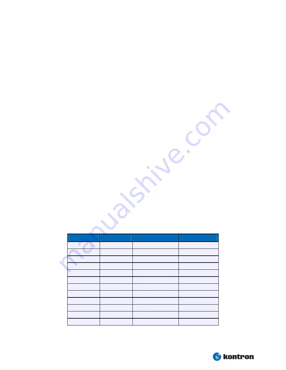
7.4.1
Standard IBM-Compatible VGA Modes
Video Mode
Type
Characters/Pixels
Colors
00h/01h
Text
40x25
16
02h/03h
Text
80x25
16
04h/05h
Graphics
320x200
4
06h
Graphics
640x200
2
07h
Text
80x25
2
0Dh
Graphics
320x200
16
0Eh
Graphics
640x200
16
0Fh
Graphics
640x350
2
10h
Graphics
640x350
16
11h
Graphics
640x480
2
12h
Graphics
640x480
16
13h
Graphics
320x200
256


