3.5"-SBC-APL V2.0 - User Guide, Rev. 2.2
www.kontron.com
// 10
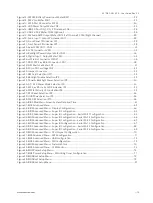
7.7. Audio Input / Output Pin Header (CN11)............................................................................................................................................ 38
7.8. Front Panel Pin Header (FP1 & FP2) .................................................................................................................................................. 39
7.9. Serial COM1 - COM6 Ports (CN17 - CN22) ......................................................................................................................................... 41
7.10. LVDS Panel Connector (LVDS1).......................................................................................................................................................... 42
7.11. Backlight Power Output Wafer (CN23) ............................................................................................................................................ 44
7.12. Digital Input / Output Wafer (CN14) ................................................................................................................................................ 45
7.13. mPCIe Socket (MPCIE1) ......................................................................................................................................................................... 46
7.14. NGFF M.2 Key B Socket (CON1) .......................................................................................................................................................... 48
7.15. SIM Interface Wafer for MPCIE1 and M.2 Key B (CN7)................................................................................................................. 51
7.16. Micro-SD Card Cage (CN3) .................................................................................................................................................................. 52
7.17. Switches and Jumpers .......................................................................................................................................................................... 53
7.17.1. SIM Card Selection (JP1)..................................................................................................................................................................... 53
7.17.2. Backlight Enable Selection (JP2) .................................................................................................................................................... 53
7.17.3. Panel & Backlight Power Selection (JP3) .................................................................................................................................... 54
7.17.4. AT / ATX Power Mode Selection (JP4) ......................................................................................................................................... 54
7.17.5. M.2 Key B Activity LED Pin Header (JP5) ...................................................................................................................................... 55
7.17.6. MPCIE Activity LED Pin Header (JP6) ............................................................................................................................................ 55
7.17.7. RTC Reset Selection (JP8)................................................................................................................................................................. 55
7.17.8. USB Power Selection (JP9) .............................................................................................................................................................. 56
7.17.9. ME F/W Selection (JP10) ................................................................................................................................................................... 56
8/
On-Board Connectors & Mating Connector Types ............................................................................................................... 58
9/
BIOS ........................................................................................................................................................................................................ 59
9.1. Starting the uEFI BIOS ............................................................................................................................................................................. 59
9.2. Setup Menus ............................................................................................................................................................................................. 60
9.2.1. Main Setup Menu .................................................................................................................................................................................. 60
9.2.2. Advanced Setup Menu ........................................................................................................................................................................ 62
9.2.3. Power Setup Menu .............................................................................................................................................................................. 76
9.2.4. Boot Setup Menu.................................................................................................................................................................................. 78
9.2.5. Security Setup Menu ........................................................................................................................................................................... 79
9.2.5.1. Remember the password ............................................................................................................................................................... 80
9.2.6. Save & Exit Setup Menu ...................................................................................................................................................................... 81
Appendix A: List of Acronyms ..................................................................................................................................................................... 82
About Kontron .................................................................................................................................................................................................. 83
List of Tables
Table 1: Component Main Data .................................................................................................................................................................... 18
Table 2: Environmental Conditions ............................................................................................................................................................ 19
Table 3: Standards and Certifications ....................................................................................................................................................... 19
Table 4: Processor Support .......................................................................................................................................................................... 20
Table 5: Memory Operating Frequencies ................................................................................................................................................. 21
Table 6: Three-displays Configurations ................................................................................................................................................... 21
Table 7: Supply Voltages ................................................................................................................................................................................ 21
Table 8: Jumper List ........................................................................................................................................................................................ 22
Table 9: Top Side Internal Connector Pin Assignment ........................................................................................................................ 22
Table 10: Rear Side Internal Connector Pin Assignment .................................................................................................................... 24
Table 11: Connector Panel Side Connector List ...................................................................................................................................... 25
Table 12: Pin Assignment HDMI Connector CN15 .................................................................................................................................. 27
Table 13: Pin Assignment DP Connector CN13 ....................................................................................................................................... 28
Table 14: Pin Assignment Ethernet Connectors CN9, CN10 ............................................................................................................... 29
Table 15: Pin Assignment USB3.0 / USB2.0 Connector CN4, CN5 .................................................................................................... 30


