background image


Accessories

[As per ISO 10294-4: 2012, NF S 61937-1: 2003 and 

NF S 61937-5: 2012]

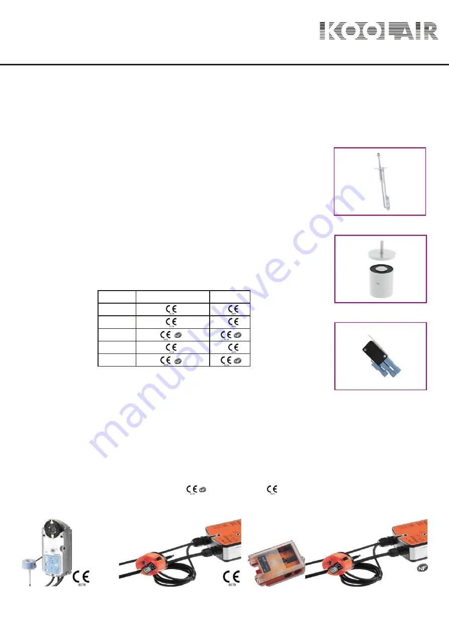
Fusible link (DAS)

Alloy type (bimetallic) fusible link, which acts when the air flow temperature exceeds 72 ºC

(EN 10294) causing the fusible link to smelt. In all the operating mechanism arrangements

it is incorporated as standard in the internal assembly of the trigger mechanism except

where a servomotor with a reset spring is fitted.

Electromagnetic coil (shunt or undervoltage release) (DAS)

There are two types: shunt release or undervoltage release.

Shunt releases are normally de-energised and act via an electric signal (electric

supply)

Undervoltage releases are normally energised and act by removing or breaking the

current supply.

Available in:

FUSIBLE LINK (DAS)

ELECTRIC COIL (DAS)

CONTACT POSITION

SIEMENS

SERVOMOTOR

(DAS)

SAFETY OPERATING DEVICES (DAS) AND ACCESSORIES

Start and end of run position contacts

Electrical devices that indicate the position of the damper, i.e. whether it is open or

closed, by connected control systems, detection modules, etc.

Protection rating ≥ IP42

PC = Start of run

FC = End of run

Servomotor with reset spring and thermoelectric fusible link (DAS)

Allows the damper to be both reset (opened) and activated (closed) remotely. Fitted with

a thermoelectric fusible link set at 72 ºC (EN 10294) and its own signalling contacts

(start and end of run).
The servomotors are supplied for 24 V operation 


  230 V operation 


available on request. KOOLAIR incorporates motors from different manufacturers

(Belimo, Siemens, etc.).

BELIMO SERVOMOTOR (DAS)

BELIMO SERV BSIA (DAS)

Voltage

Shunt release

Ruptura

220 V.a.c.

24 V.a.c.
24 V.d.c.
48 V.a.c.
48 V.d.c.


Series SF

13

Summary of Contents for SCFC-GD

Page 1: ...series Fire dampers SF www koolair com...

Page 2: ...rcular fire dampers CONTENTS Description 2 Declared performance 4 Applications 6 Model and dimensions 8 Accessories 13 Installation 14 Operating Mechanisms 19 Special finishes 22 Technical data 23 Cod...

Page 3: ...xceeds 72 C It is reset manually in all instances except when incorporating a servomotor with return spring and a thermoelectric fusible link calibrated at 72 C All dampers comply with requirements of...

Page 4: ...C to comply with EN 1751 Motor driven fire dampers can be integrated into the building management system BMS and or fire panel with the KOOLCOM system from KOOLAIR To guarantee the correct fire damper...

Page 5: ...6 SCFR GD CPR 2591 16 SFR3K1GT CPR 1493 14 Dimensions mm Dimensions mm Construction details Construction details Installation location Installation location Installation location Installation Installa...

Page 6: ...EI 90 2 sheets of laminated fireproof plasterboard ref KNAUF cortafuego DF thickness 12 5 mm Rock wool panel ref ProRox SL960 ROCKWOOL 2 sheets of laminated fireproof plasterboard ref KNAUF cortafuego...

Page 7: ...0 100 200 300 400 500 600 650 700 800 H mm SCFR PD SCFR GD SCFR GD L mm 200 300 400 500 600 700 800 100 200 300 400 500 600 H mm SCFR PD Applications FIXED WALL EI 180 EI 180 ve i o S RECTANGULAR FIXE...

Page 8: ...0 125 160 200 250 315 355 400 450 500 560 630 650 700 710 750 800 SCFC GD EI 120 S SCFC PD EI 120 S SCFC GD EI 180 S mm 100 125 160 200 250 315 355 400 450 500 560 630 SCFC PD SCFC GD Applications SLA...

Page 9: ...are available in standard sizes duct size with a length L dimension from 200 to 800 mm increasing in 50mm increments and a height dimension H from 100 to 600 mm increasing in 50mm increments 1 Galvan...

Page 10: ...dimensions 1 Galvanised steel frame 2 Damper blade 3 Mechanism motor housing 4 Intumescent seal 5 30 mm flange Drive shaft SCFR GD fire dampers are available in standard sizes duct size with a length...

Page 11: ...R3K1GT fire dampers are available in standard sizes duct size with a length L dimension from 200 to 1500 mm increasing in 50mm increments and a height dimension H from 200 to 800 mm increasing in 50mm...

Page 12: ...dimensions The standard dimensions duct dimensions of SCFC PD fire dampers are 100 125 160 200 250 315 and 355 mm Drive shaft nom inal 2 1 Galvanised steel frame 2 Blade 3 Mechanism motor housing 4 In...

Page 13: ...CFC GD Model and dimensions The standard dimensions duct dimensions of SCFC GD fire dampers are 400 450 500 560 630 650 700 710 750 and 800 mm nominal 2 nominal 48 Drive shaft 1 Galvanised steel frame...

Page 14: ...in FUSIBLE LINK DAS ELECTRIC COIL DAS CONTACT POSITION SIEMENS SERVOMOTOR DAS SAFETY OPERATING DEVICES DAS AND ACCESSORIES Start and end of run position contacts Electrical devices that indicate the...

Page 15: ...or partition As such when the fire damper blade is in the closed position it will be exactly vertical in the firewall as if it were an extension of this wall as required by UNE EN 1366 2 Likewise the...

Page 16: ...and uprights in 400 mm spacing Pladur FOC 12 5 Pladur FOC 12 5 Pladur FOC 12 5 Pladur FOC 12 5 TYPE A Pladur FOC 12 5 TYPE B Type A Type A Type B Type B Type A Pladur FOC 12 5 NOTE The distance betwee...

Page 17: ...ly to horizontal and vertical dampers There must be a minimum separation of 75 mm between fire dampers and building elements There must be a minimum separation of 200 mm between fire dampers The slot...

Page 18: ...device at 0 Airflow direction is not critical ve i o o ho i o Manual device at top Manual device at 180 Manual device at bottom Motor driven Motor driven Motor driven device at 0 Motor driven device...

Page 19: ...l device at 0 Manual device at top Manual device at 180 Manual device at bottom Motor driven Motor driven Moto driven device at 0 Motor driven device at top Motor driven device at 180 Motor driven dev...

Page 20: ...en alloy fuse is triggered by temperatures over 72 C The damper is reset opened by pressing the E shaft until the electromagnet is energised undervoltage release or de energised shunt release and inse...

Page 21: ...ith return spring A or D Manually inserting the lever in hole A and turning clockwise Damper is closed operated by providing electric supply to shunt release or by switching off supply to undervoltage...

Page 22: ...r 24 48 V AC DC to the same terminals as shown in the electrical wiring diagram Manually inserting the lever in hole A and turning clockwise Damper is closed operated by providing an electrical supply...

Page 23: ...ssible to supply rectangular and circular dampers with transformation spigots on request as a non standard finish These couplings may require a longer frame length than the defined standard in order t...

Page 24: ...300 AL m2 0 19 0 14 0 14 0 14 0 14 0 14 0 14 0 14 0 14 0 14 0 14 0 14 0 14 kp 4 4 3 3 3 3 2 2 2 2 2 1 1 kdB A 450 0 085 0 106 0 128 0 149 0 170 0 191 0 213 0 234 0 255 0 276 0 298 0 319 0 340 AL m2 0...

Page 25: ...ect a 600 x 500 mm SCFR PD damper We use the table on the previous page to find the following data AL 0 285 m2 kp 0 14 kdB A 1 The technical data to achieve a flow rate of 5450 m3 h is required Referr...

Page 26: ...1 0 0 0 0 kdB A 800 0 150 0 188 0 225 0 263 0 300 0 338 0 375 0 413 0 450 0 488 0 525 0 563 0 600 AL m2 0 75 0 67 0 60 0 54 0 49 0 44 0 40 0 37 0 34 0 30 0 28 0 25 0 23 kp 3 2 2 2 1 1 1 1 0 0 0 0 0 k...

Page 27: ...0 0 0 0 kdB A 500 0 383 0 405 0 428 0 450 0 473 0 495 0 518 0 540 0 563 0 585 0 608 0 630 0 653 0 675 AL m2 0 40 0 38 0 35 0 34 0 32 0 30 0 28 0 27 0 25 0 23 0 22 0 21 0 19 0 18 kp 1 1 1 0 0 0 0 0 0 0...

Page 28: ...ct a 1000 x 300 mm SCFR GD damper We use the table on the previous page to find the following data AL 0 25 m2 kp 0 56 kdB A 2 The technical data to achieve a flow rate of 5500 m3 h is required Referri...

Page 29: ...533 0 572 AL m2 0 48 0 43 0 39 0 37 0 34 0 33 0 31 0 30 0 29 0 28 0 27 0 26 0 26 kp 11 7 5 3 1 0 0 1 2 3 4 5 6 kdB A 900 0 120 0 163 0 207 0 251 0 295 0 339 0 382 0 426 0 470 0 514 0 558 0 601 0 645 A...

Page 30: ...0 45 50 0 25 0 35 0 50 0 90 veff m s kp P Pa 5000 7500 10000 12500 15000 25000 3000 2000 1000 800 600 400 200 1 10 veff m s 0 01 0 10 1 00 A L m 2 Q m3 h 0 20 20 55 60 LwA dB A 17500 20000 22500 Techn...

Page 31: ...m s 20 25 Technical data Selection example For the given duct dimensions we select a SCFC PD damper with a diameter of 200 mm for a flow rate of 500 m3 h Referring to the diagram above using this flo...

Page 32: ...25 710 750 800 Technical data Selection example For the given duct dimensions we select a SCFC GD damper with a diameter of 500 mm for a flow rate of 5000 m3 h Referring to the diagram above using th...

Page 33: ...FC PC MOTOR 24 48 RESET B IMP 48 V AC FC PC MOTOR 24 48 RESET B IMP 220 V AC FC PC MOTOR 110 230 RESET B RUPT 24 V CC FC PC MOTOR 24 RESET B RUPT 48 V CC FC PC MOTOR 24 48 RESET B RUPT 24 V AC FC PC...

Page 34: ...THIS CATALOG IS INTELLECTUAL PROPERTY The partial or total reproduction of its contents is forbidden without the express and authoritative authorisation of KOOLAIR S A CEN SF 1117 00 Series SF 33...

Page 35: ...KOOLAIR S A Calle Urano 26 Poligono industrial n 2 La Fuensanta 28936 M stoles Madrid Espa a Tel 34 91 645 00 33 Fax 34 91 645 69 62 e mail info koolair com www koolair com...

Reviews: