background image

6

    Introduction

LED Display - Alarm Settings

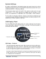
By default, the Koolance audio alarm will sound if the primary sensor reaches 
55ºC (131ºF). When the system alarm sounds, the LED temperature will 

fl

 ash in 

the display and the radiator fans will increase to 100% power.

To change this setting with the LED Display, press and hold 

 + 

 together for 

3 seconds. The alarm temperature will begin 

fl

 ashing. You may change this value 

from 0ºC (32ºF) up to 99ºC (210ºF). The normal temperature reading will resume 
if you do not press any buttons for 4 seconds.

To reset the temperature alarm to the default (55ºC / 131ºF) setting, press and 
hold the 

ºC/F

 button until “dEF” 

fl

 ashes in the display. NOTE: This will also reset 

the fan speed mode to “auto”.

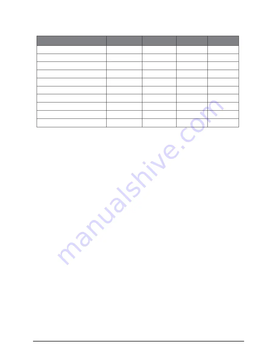
Auto Mode

Manual Mode

Fan Power %

Total CFM

Fan RPM

0 - 35ºC   (32 - 95ºF)

1

30

84

720

36 - 37ºC   (97 - 99ºF)

2

35

99

840

38 - 39ºC   (100 - 102ºF)

3

40

114

960

40 - 41ºC   (104 - 106ºF)

4

45

129

1080

42 - 43ºC   (108 - 109ºF)

5

50

141

1200

44 - 45ºC   (111 - 113ºF)

6

60

171

1440

46 - 47ºC   (115 - 117ºF)

7

70

198

1680

48 - 49ºC   (118 - 120ºF)

8

80

225

1920

50 - 51ºC   (122 - 124ºF)

9

90

255

2160

52 - 99ºC   (126 - 210ºF)

10

100

282

2400

Details on fan modes are as follows:

Summary of Contents for ERM-3K4U

Page 1: ...otected by U S Patents 6 664 627 6 313 990 6 234 240 5 731 954 Other Technology Pending U S World Wide Patents Superior Liquid Cooling Systems English v1 00 ERM 3K4U User s Manual ERM 3K4U User s Manu...

Page 2: ...to equipment PROHIBITED Indicates a prohibited action PROHIBITED USE This product is designed developed and manufactured as contemplated for general use including without limitation general office use...

Page 3: ...koolance com CAUTION Koolance Incorporated can not be held responsible for any damage to your system due to misconfiguration or incorrect installation If there is any point of installation that you do...

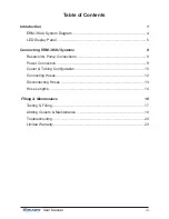
Page 4: ...Panel 5 Connecting ERM 3K4U Systems 8 Reservoir Pump Connections 9 Power Connection 9 Cooler Tubing Configuration 10 Connecting Hoses 12 Disconnecting Hoses 13 Hose Lengths 14 Filling Maintenance 16 T...

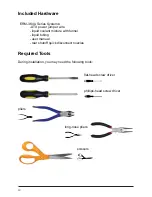
Page 5: ...olant mixture with funnel liquid tubing user manual rear shutoff quick disconnect nozzles Included Hardware flat head screw driver phillips head screw driver pliers scissors Required Tools During inst...

Page 6: ...1 User Manual Chapter1 Introduction...

Page 7: ...ften run at a higher speed Many people have therefore come to equate high performance with high noise As systems continued to be upgraded the required heat sinks simply got larger and louder Liquid co...

Page 8: ...your computer if you are not there to do so But Koolance s innovations extend beyond just cooling features Our safe patent pending CPU Retention Clip places even pressure across the CPU protecting the...

Page 9: ...ank is transparent for easy liquid level monitoring throughthe top or side windows It is filled through a small metal plug on the top side Flow Meters Each pump is paired with a flow meter viewable th...

Page 10: ...ure or another available component LED Display Fan Speed This option adjusts the radiator fan speed Higher speeds can improve performance but will produce more noise There is 1 automatic and 10 manual...

Page 11: ...rature reading will resume if you do not press any buttons for 4 seconds To reset the temperature alarm to the default 55 C 131 F setting press and hold the C F button until dEF flashes in the display...

Page 12: ...To rotate the display remove the ERM 3K4U top cover above the reservoir both rack handles and ears and both front bezel side screws This enables the removal of the front bezel and provides access to...

Page 13: ...8 Connecting ERM 3K4U Systems Chapter2 Connecting ERM 3K4U Systems...

Page 14: ...ultaneously Each pump inlet outlet is typically configured as a separate loop to maintain coolant pressure and flow rate That is one or more heat sources from one or more computers can be chained in s...

Page 15: ...he best overall performance For an ERM 3K4U unit a single loop connects to the same pump inlet and outlet This configuration can be duplicated on each pump Metric Emperical 6 mm 1 4 in 10 mm 3 8 in 13...

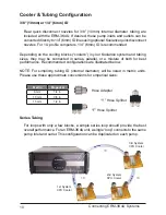
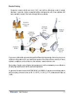
Page 16: ...e HD Cooler 6mm Koolance Splitter Koolance Splitter If you are comfortable experimenting with different tubing setups there may be more optimal configurations for your particular system Koolance offer...

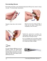
Page 17: ...nozzle Tighten the connection by sliding the compression fitting down over the nozzle and screwing it securely by hand Do not overtighten the nozzle fitting Most connections are leak resistant even be...

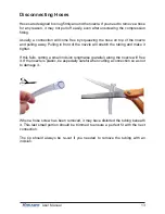
Page 18: ...in front of the nozzle will stretch the tubing and make it tighter If this fails cutting a small incision lengthwise parallel along the nozzle will free it If the nozzle is plastic be especially care...

Page 19: ...y the outlet of the cooling system or radiator will connect with your CPU Cooler but this is completely optional With one of the connected hoses roughly estimate the length you will need to your first...

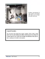
Page 20: ...here are no longer any open tube ends Liquid Coolers You should now install the liquid coolers CPU GPU Hard Drive etc to your hardware before continuing this User Manual Please refer to your cooler ki...

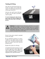
Page 21: ...enance WARNING The ERM 3K4U pumps can not be run dry for any period of time Never power on the cooling system without sufficient liquid in the reservoir Dry running and thereby damaging the pump is no...

Page 22: ...m and keep all liquids away from computer hardware and power cables In case of emergency during installation immediately unplug the computer s rear power supply cable Dry the system thoroughly before...

Page 23: ...ial bleeding process If there is an air gap in the pump during power up the pump may not be able to move it resulting in an absence of coolant flow The pumps need to be burped to avoid this situation...

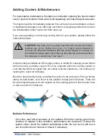
Page 24: ...el directly beneath the work area within the chassis to absorb any free liquid Radiator Performance Over time dust will accumulate on the radiator While the cooling system may continue to operate in t...

Page 25: ...as been removed and the CPU tension screw and or bracket are positioned correctly see the CPU Cooler s Instructions Also check that there are no blocks twists or crimps in the tubing system Finally a...

Page 26: ...to configure their own coolers and clamps it is possible a connection was not properly sealed however unlikely If you can see liquid somewhere on the tubing or at the bottom of the chassis computer co...

Page 27: ...ected or faulty If the sensor can not be detected the cooling system alarm will sound The sensor will need to be reconnected inside the unit or else replaced Please visit our support web page for cont...

Page 28: ...er for damage resulting from warranty service performed by a non authorized repair service No responsibility is assumed for any special incidental or consequential damages due to a defective Koolance...

Page 29: ...www koolance com ISO 9001 Printed in Korea...

Reviews: