background image

2

3

User Manual

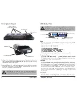
Exos System Diagram

Reservoir & Pump

Radiator Cooling Fans

(quantity depends on model)

Coolant Inlet

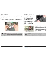
Power Connection

LED Display Panel

Coolant Outlet

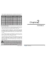
Current Mode

Value

Mode Select

Display in ºC or ºF

Decrease Setting

Increase Setting

    System Features

CAUTION:

 Due to electrical tolerances, the lowest pump speed set-

tings may stop the pump from running. Be sure the pump continues 
to run when operated at lower speeds.

!

Radiator - 

The primary heat exchanger is the main cooling element, and provides 

high thermal dissipation in a relatively small area. Inside, a metal web of louver 
fins stretch between flat liquid pipes.

Reservoir & Pump - 

The coolant tank is transparent for easy liquid-level monitoring 

through the front window. It is filled through a small metal fill port on top. The 
reservoir is illuminated for easy observation.

LED Display Panel

CAUTION:

 This cooling system allows full user control of hardware 

safety settings, such as audio alarm, shutdown, and pump speed. 

Please be sure to configure your LED Display Panel properly, or dam-

age to your computer, data, and/or equipment could result.

!

Modes

There are seven display options. All are reached by continually pressing the SET 
(mode select) button:

1. Temperature sensor #1 is displayed
2. Temperature sensor #2 is displayed
3. Temperature sensor #3 is displayed
4. All temperature sensors are cycled automatically
5. Fan setting is displayed (mode “F” is shown)
6. Pump setting is displayed (mode “P” is shown)
7. All temperatures, fan, and pump settings are cycled automatically

Temperature Sensors

This cooling 

system can monitor up to 3 included temperature sensors. The first 

LED digit indicates which sensor channel is currently displayed in the temperature 
reading. To cycle through sensors, press SET.

Fan Speed

This option adjusts the radiator fan speed. Higher speeds can improve performance, 
but will produce more noise. There is 1 automatic and 10 manual fan settings (1-
10). From the fan (“F”) or any cycle mode, press the 

 or 

 buttons to adjust fan 

settings, or hold down an arrow to skip to the lowest or highest mode directly.

Automatic mode will adjust the fans for you based on temperature values from 
sensor #1. This mode is reached by lowering the fan setting to “0” (

Aut

 / 

A

 will 

be displayed).

Pump Speed

There are 10 manual pump settings (1-10). From the pump (“P”) mode, press

Summary of Contents for EX2-1055

Page 1: ...990 6 664 627 7 167 366 7 295 436 Other Technology Pending U S World Wide Patents Superior Liquid Cooling Systems English v1 0 www koolance com ISO 9001 Printed in Korea EX2 755 EX2 1055 User s Manual...

Page 2: ...nal use and household use but is not designed developed and manufactured as contemplated for use accompanying fatal risks or dangers that unless extremely high safety is secured could lead directly to...

Page 3: ...use of this product Additionally adding liquid coolers and other components to computer hardware may void the hardware manufacturer s original warranty If you have any specific questions on warranty...

Page 4: ...re sensors and ATX lead Rubber foot pads ATX power jumper wire User Manual Included Hardware flat head screw driver phillips head screw driver pliers scissors Required Tools During installation you ma...

Page 5: ...our computer data and or equipment could result Modes There are seven display options All are reached by continually pressing the SET mode select button 1 Temperature sensor 1 is displayed 2 Temperatu...

Page 6: ...l close the ATX pass through wire relay For a computer this is equivalent to holding in the power button for several seconds to force it to shut down With default alarm settings this means the shutdow...

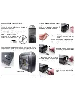
Page 7: ...ugh the metal foot loops below the unit Rubber Foot Pad Attachment Straps External Nozzles Power Cable Cut tubing into two segments You will need to connect each to the rear nozzles Each hose connecti...

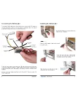
Page 8: ...connect withATX computers through an available card slot It is responsible for inlet outlet tubes the external power cable temperature sensors and shutdown lead There are 5 main internal connections t...

Page 9: ...ive the chassis power button directly CAUTION The auto shutdown safety feature of your cooling system will not function properly without connecting the ATX pass through lead Power Connection The cooli...

Page 10: ...heat exchanger This means for most loops you don t need to worry about hot water moving from one block to the next It gets only a little warmer throughout the entire loop Generally series is the simp...

Page 11: ...tions will be labeled Generally the outlet will connect first with your CPU Cooler or the most temperature sensitive device Coolant Outlet Coolant Inlet Parallel Loops Parallel loops are normally used...

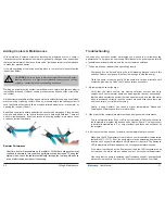
Page 12: ...hapter 3 Filling Maintenance WARNING The cooling system s pump can not be run dry for any period of time Never power on the computer or cooling system without sufficient liquid in the reservoir Dry ru...

Page 13: ...t it to the lowest level during this time Allow the pump to run until the liquid noise subsides During this process cooling systems often need to be tilted gently to allow air to escape from the pump...

Page 14: ...To help avoid unnecessary RMA issues we have prepared this list of possible operational problems and their most common solutions 1 The pump does not appear to be operating properly Pumps need to be b...

Page 15: ...d remove the component In many cases the hardware will be fine after allowing it to dry However the system should not be operated until you have discovered where the leak is coming from and can repair...

Page 16: ...age resulting from warranty service performed by a non authorized repair service No responsibility is assumed for any special incidental or consequential damages due to a defective Koolance product In...

Reviews: