background image

24

4. After the system has been on for a while, the temperature alarm sounds...

Make sure the LED temperature is at or above your preset alarm temperature 
(default is 55ºC, 131ºF). If not, the audio alarm may in fact be your mother-
board’s BIOS alarm. If the system is not exhibiting signs of overheating (see 
#2 in 

Troubleshooting

), this temperature monitor may need to be disabled 

to ignore false readings by BIOS. The Koolance LED temperature will fl ash 
whenever the cooling system alarm sounds.

If the alarm sounds within a few seconds after a cold boot-up, or the LED 
temperature does not reach the alarm preset, the control board/pumps may 
be malfunctioning. Please visit our support web page for more information.

Verify that the pumps are operating (see Troubleshooting #1), and that liquid 
fl ow is present in the reservoir. Note that if the reservoir was over-fi lled during 
system assembly, this procedure is not possible since there  will be no neces-
sary air gap.

5. My system has boot-up problems, or does not turn on...

The majority of these problems are not related to the Koolance case, but 
hardware or confi guration issues. In a new system, a problem with the RAM, 
motherboard, power supply, video card, processor, or monitor can cause the 
system to appear not to boot-up properly.

If the top Radiator fans do not spin, or if the front LED Display Panel does not 
light-up, check to see if your motherboard has a power indicator LED on the 
board. This is usually a green light next to the ATX power connector. If unlit, 
power is not getting to the motherboard.

The Power Circuit (or Exos Slot Interface Adapter) should be checked to make 
sure all connections are plugged-in, especially the 12V 4-pin power supply 
connection. Also be sure if your power supply has a rear power switch, that 
it is in the ON (“-”) position, and switched to the appropriate regional current 
(115VAC or 220VAC).

Another possibility is that the motherboard is shorting-out electrically on the 
chassis. Remove the motherboard, and verify that the stand-offs are properly 
installed. Lastly, check that the IO shield (the thin aluminum rear motherboard 
ATX port plate) is not bent backwards around the motherboard, possibly short-
ing a component.

If further problems persist, you are likely having a separate hardware issue. 

Summary of Contents for Exos-2

Page 1: ...Protected by U S Patents 6 664 627 6 313 990 6 234 240 5 731 954 Other Technology Pending U S World Wide Patents Superior Liquid Cooling Systems English v1 00 Exos 2 User s Manual Exos 2 User s Manual...

Page 2: ...ousehold use but is not designed developed and manufactured as contemplated for use accompanying fatal risks or dangers that unless extremely high safety is secured could lead directly to death person...

Page 3: ...olance com CAUTION Koolance Incorporated can not be held responsible for any damage to your system due to miscon guration or incorrect installation If there is any point of installation that you do no...

Page 4: ...tioning the Exos 8 External Nozzles Power Cable 9 Connecting the Slot Adapter 10 Installing the Slot Adapter 11 Power Connection 12 ATX Power Switch 13 Cooler Tubing Con guration 14 Disconnecting Hose...

Page 5: ...er foot pads ATX power jumper wire re ll funnel liquid coolant mixture liquid tubing user manual Included Hardware at head screw driver phillips head screw driver pliers scissors Required Tools During...

Page 6: ...1 User Manual Chapter1 Introduction...

Page 7: ...fan is often run at a higher speed Many people have therefore come to equate high performance with high noise As systems continued to be upgraded the required heat sinks simply got larger and louder L...

Page 8: ...tures Our proprietary power control board constantly monitors liquid temperature sounding an alarm if it should get too high and even turning off your computer if you are not there to do so But Koolan...

Page 9: ...y bringing the system to shut itself down see LED Display Panel Power Circuit Board Beneath the reservoir the Power Circuit is responsible for a number of tasks including powering the pumps LED displa...

Page 10: ...rom sensor 1 This mode is reached by lowering the fan setting to 0 Aut A1 will be displayed Details on fan modes are as follows CAUTION Exos 2 systems allow full user control of hardware safety settin...

Page 11: ...the fan speed mode to auto Introduction CAUTION Although alarm settings can be set separately for each sensor safety shutdown mode will only respond to sensor 1 It is highly recommended for this sens...

Page 12: ...7 User Manual Chapter2 Connecting Exos 2 Systems...

Page 13: ...eet 1 2 meters should be an acceptable distance for most Exos con gurations Extra tubing can be purchased from Koolance com or your local reseller Connecting Exos 2 Systems Rubber foot pads are includ...

Page 14: ...compression tting hose screw to keep it secure To connect these components rst thread a hose screw onto the tube end Once the hoses are connected plug the external power cable into the Exos Squeeze t...

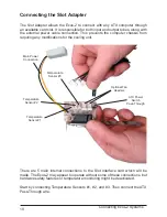
Page 15: ...uiring any modi cations for the cooling unit There are 5 main internal connections to the Slot Interface card which will be made The Exos 2 may appear to operate without some of these connections but...

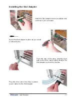
Page 16: ...uter Screw the Slot Adapter in place as you would a normal device From the rear of the case carefully feed both ends of the liquid tubing through the Slot Adapter and into the chassis Plug the other e...

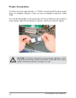
Page 17: ...dedicated external AC power cable Connect the Slot Adapter s main power plug 12 Volt 4 pin Molex to the computer s power supply Without this important connection the Exos 2 will NOT operate CAUTION Th...

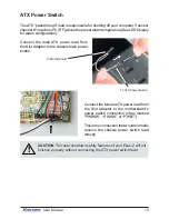
Page 18: ...d from the Slot Adapter to the chassis main power button Connect the female ATX power lead from the Slot Adapter to the motherboard s power switch connection often marked PWRSW PWSW or PWBT This is th...

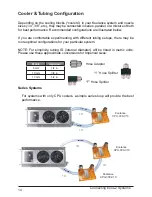
Page 19: ...l con gurations for your particular system NOTE For simplicity tubing ID internal diameter will be listed in metric units Please use these approximate conversions for Imperical sizes Cooler Tubing Con...

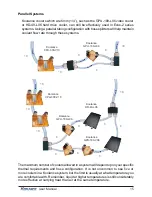
Page 20: ...derably more effective at carrying heat than air at the same temperature Parallel Systems Koolance coolers which are 6mm 1 4 such as the GPU 180 L06 video cooler or HD 40 L06 hard drive cooler can sti...

Page 21: ...the nozzle and pulling away If this fails cutting a small incision lengthwise parallel along the nozzle should free it When a hose screw has been removed it may have distorted the tubing beneath it Th...

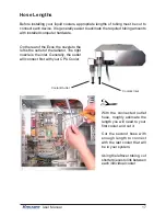
Page 22: ...nozzle to the left is the outlet of the radiator The right nozzle is the inlet Generally the outlet will connect rst with your CPU Cooler With the connected outlet hose roughly estimate the length yo...

Page 23: ...ny open tube ends Liquid Coolers You should now install the liquid coolers CPU GPU Hard Drive etc to your hardware before continuing this User Manual Please refer to your cooler kit s individual insta...

Page 24: ...19 User Manual Chapter3 Filling Maintenance...

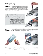
Page 25: ...ack of liquid WARNING The liquid coolant is electrically conductive Use cau tion when filling the system and keep all liquids away from computer hardware and power cables In case of emergency during i...

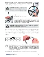
Page 26: ...ON Jumping the incorrect ATX power supply pins can cause permanent damage to the power supply Make sure the AC power cord is attached to the power supply If the power supply has a rear switch it must...

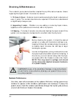
Page 27: ...over hanging Hold a 2 liter container below the reservoir to capture liquid Unscrew the re ll tap to begin draining the system In some con gurations air may not be able to enter the system and will pr...

Page 28: ...emperature reboots shut downs etc there may be a problem with your system These same symptoms can also be attributed to a faulty power supply and other internal hardware Verify that the liquid coolers...

Page 29: ...roblems are not related to the Koolance case but hardware or con guration issues In a new system a problem with the RAM motherboard power supply video card processor or monitor can cause the system to...

Page 30: ...chipset power connectors There is sometimes an option to disable these fan connections in BIOS but you may have to boot up with a fan attached initially to disable this setting If the system is not b...

Page 31: ...damage resulting from warranty service performed by a non authorized repair service No responsibility is assumed for any special incidental or consequential damages due to a defective Koolance produc...

Page 32: ...www koolance com ISO 9001 Printed in Korea...

Reviews: