12
Main Landing Gear:
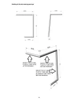
Bend the main landing gear from the ø 2 mm steel wire according to the drawing at the end of this
manual (second piece mirrored).
When bending, insert the plastic tube with inside ø 2 mm in the 60-
mm section of the wire and the big plastic and aluminum tube on the 80-mm section of the wire (these
will serve as the landing gear leg dummies). After bending, the tubes can no longer be pushed onto
the wire.
Insert a plastic tube with inside ø 2 mm on the 40-mm section.
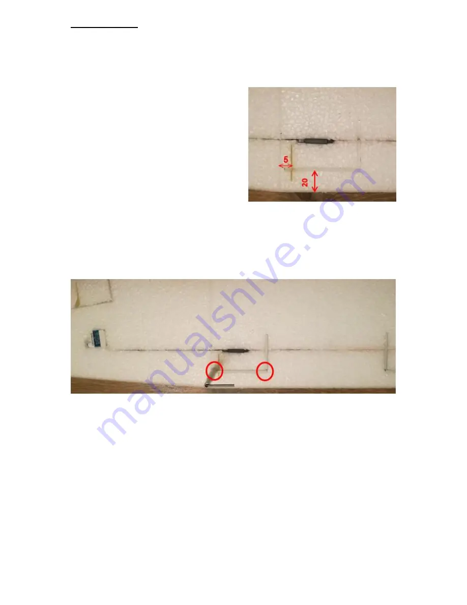
Both landing gear legs are attached only in the wing
center section. Cut an L-shaped groove (according to
the landing gear legs) into the wing center section.
The landing gear legs come out of the wing at the
points where the wing center part is joined to the
outer wing parts, 20 mm from the leading edge of the
wing center part.
Important is the fiberglass stiffener of the landing
gear approx. 5 mm from the joint of the wing center
section and wing outer parts. This stiffener must be
cut so deeply that it is flush with the underside of the
wing and its shorter side (from the groove for the
landing gear) is towards the leading edge.
Glue this
stiffeners with CA before gluing the landing gear. The
depth of the L-shaped groove in the wing must be as
deep as the groove in the stiffener.
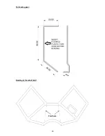
It is recommended to apply some narrow tape to the plastic pipes
on the corners of the landing gear (marked in the picture below) so that no CA glue can flow into the
tubes, because the wire must remain freely movable in the pipes, otherwise the landing gear will tear
from the wing during harder landings. This ensures a torsional suspension of the landing gear.
The landing gear can be glued after painting the model.
Use a small piece of plastic pipe glued with CA as wheel lock (alternatively use stop collars).
A trick
not to glue
the wheels to the wire is to pierce a piece of plastic bag on the landing gear wire and then
glue the plastic tube with CA. Secure the tail wheel with a piece of pushrod tube in the same way.


