15
Assembly of the Model:
Draw a center line on the leading and trailing edge of
the wing, make sure the wing fits well on the fuselage
(pull the servo cables to the receiver cutout through
the fuselage).
If everything fits, glue it together with PU glue + CA,
as described above.
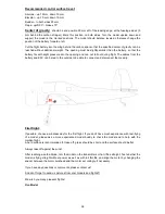
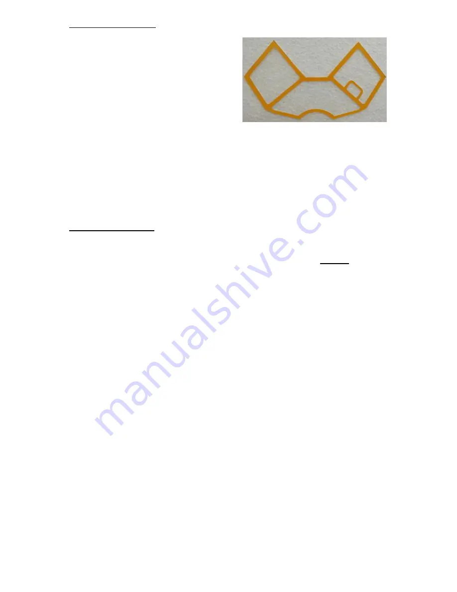
Paint the self-adhesive sticker of the cockpit frame
with the same color as the model before applying to
the windshield.
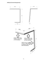
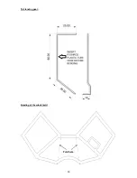
After the paint is dry, apply this sticker to the
windshield and bend it as shown in the drawing at the end of this manual.
Bend the pillars for the cockpit
from the steel wire ø 1 mm, both of one piece of wire. Insert the
pushrod tube onto the wire before bending, it will then be easier to glue it to the EPP and to paint the
pillars. Their shape is best estimated after applying the windshield to the fuselage. Glue the pillars in
place when everything fits. The windshield will be installed after painting the model. It is sufficient to
attach the windshield with pins with small heads at the corners, so that it is removable in case you
need access to the receiver or servos. The rear windows are pressed into the fuselage after painting
the model and glued with CA gently (apply the glue with a needle, for example), so that no white stain
is created.
Finishing of the model:
Sand the model with a sanding mesh for drywall for a better finish, if required.
Paint the model with either water-based paints or spray paint
– we recommend
Montana
spray paint,
it is cheap and has excellent adhesion (or DupliColor, PrismaColor,
…).
The model on the pictures is painted with spray paint DupliColor with color code
RAL 1021
. From
other paint manufacturers also RAL 1023 may look good.
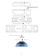
Anti-slip strips for the wings and tail numbers in the correct sizes are ready to print 1:1 at the end of
this manual. If you wish to make your own tail numbers, create it in MS Word: font is
Arial Narrow
,
switch on
Bolt
, font size for the wings is
145
and for the fuselage
88
.
Connect the complete electronics and check the function. Check the downthrust and sidethrust of the
motor, slightly down and to the right in flight direction. Secure the servo levers with screws after
centering them and glue the servos with hot glue gun in place. Connect the servo levers, control horns
and flaps by the steel wire pushrods with Z-Bends on one side and variable linkage connectors on the
servo side (or, alternatively, also Z-Bends).


