4
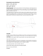
Place the horizontal stabilizer on one part of the
fuselage (with the control horn in the elevator
facing the inside of the fuselage) and mark the
position where the control horn will move during
elevator operation (with enough space around the
control horn).
Do the same also on the other part of the
fuselage.
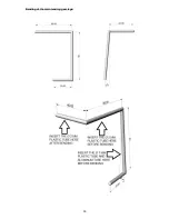
Cut the space for the control horn using a sharp
knife of hot soldering iron in both fuselage parts.
The control horn must move freely with the
installed pushrod with Z-Bend.
Right-side part of the fuselage:
Create a Z-Bend on one end of the steel
wire
ø 1 mm for the elevator and push it
through the plastic pushrod tube.
Insert the Z-Bend in the control horn from
the right side (seen in direction off light) and
place it together with the horizontal stabilizer
on the right-side part of the fuselage. The
pushrod tube hast to run from the elevator
control horn all the way to the cockpit, where
the elevator servo will be placed. Choose an
appropriate position of the servo according
to its size and the size of its lever. Guide the
pushrod tube with the pushrod to the servo
lever
in
the
easiest
way,
without
unnecessary bends.
Prepare an opening for the servo that is 1 mm smaller from all
sides than the servo. This gives the servo a tight fit. The servo
should be cut so deeply that it is flush with the surface of the
cockpit. The servo is glued in after centering the lever and
painting the model. Prepare a groove for the servo cable
towards the receiver cavity.
Prepare a groove for the pushrod tube inside the fuselage and press in the pushrod tube.
Remove the wire from the elevator control horn, leave it in the fuselage and cut the wire (with reserve)
on the side of the cockpit so that a Z-bend to the servo lever is possible later.
Alternatively, a variable
linkage connection (Pushrod connector - linkage stopper) can be used. Also shorten the pushrod tube.


