background image

 - 16 -

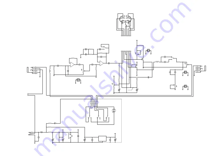
CIRCUIT DIAGRAM

R3
100

C1

100uF/16V

1

3

2

VR1A

10K A

D1

1S3

C2

0.01uF FILM

2

3

1

CON1

LD-0202A-2.0

Q1

2SK303L

S

R

SS

TS

T

RS

J2

LJB0664-6

-

2

+

3

1

U1A

NJM072D

R2
10

R4

10K

R5

10K

R6
10K

R1

2M

S

R

SS

TS

T

RS

J1

LJB0664-6

C4

1uF FILM

C6

0.1uF  FILM

C8A

0.047uF FILM

1

3

2

VR5A

100K A

2

1

3

SW1A

FK3L

5

4

6

SW1B

FK3L

8

7

9

SW1C

FK3L

R18
1K

1

3

2

VR3

10K B

1

2

3

4

5

6

7

8

CN2

B8B-ZR-3.4

1

2

CN4

CN02

C3

330uF/25V

C13

330uF/25V

C18

220uF/10V

C15A

1uF FILM

R15

2.4K

R16
10K

1

3

2

VR4A

500K B

R14

100K

R12

6.8K

R13

33K

C14

0.1uF

C17

0.1uF

R10A
4.7K

R9

51K

-

6

+

5

7

U1B

NJM072D

4

8

U1C

NJM072D

10

14

17

7

4

9

1 2

16

8

V1

6P1

R7

2M

C10

100PF B

1

3

2

VR2A

10K A

R11
150K

C11

1uF FILM

R17

75

+3.3V

+3.3V

+3.3V

GND

VCC

C12

100uF/16V

BIAS

GND

BIAS

GND

GND

GND

GND

VCC

GND

GND

R20
0

ZD1

GDZJ4.7C

[ GAIN ]

[ TONE ]

[ BIAS ]

[ VOLUME ]

[ TUBE GAIN ]

[ INPUT ]

[ OUTPUT ]

C20

0.1uF

L1

BL01RN1A2A2B

L2

BL01RN1A2A2B

C

W

C

W

C

W

C

W

C

W

7

8

VR1B

10K A

GND

7

8

VR2B

100K A

GND

7

8

VR4B

500K B

GND

7

8

VR5B

10K A

GND

C21

0.1uF

1 2 3 4 5 6

CN7A

B6B-PH-K-S

1 2 3 4 5 6 7 8

CN1

B8B-ZR-3.4

R26
220K

Q2

2SK303L

VCC

R27

2.4K

GND

C22

1uF FILM

R25

33K

C24

47uF/16V

GND

GND

GND

GND

IN

1

3

OUT 2

GND

U3

LP2950L-3.3V

C25

100PF B

[ 9V Battery ]

( 4.5V )

( 9V )

( 9V )

( 9V )

0.7V

1 2 3 4 5 6

CN7B

06P-SJN

LED1

333-2SURD-S530-A3

C8B

OPEN

R10B
OPEN

C5

82PF B

5

4

6

SW2B

MS-22D10

C15B

0.047uF FILM

2

1

3

SW2A

MS-22D10

C9A

0.1uF  FILM

C9B

OPEN

GND

[ WIDE ]

[ WIDE ]

[ ON ]

[ OFF ]

[ ON ]

[ OFF ]

[ LOW ][ GAIN ]

[ TONE ]

Summary of Contents for Nu:Tekt OD-S

Page 1: ...Checking the parts 5 Assembly Parts List 6 Assembly 7 Adjusting and setting the main circuit board 9 Operation Check 9 Troubleshooting 9 Part Names and Functions 10 Specifications 10 Recommended Settings 11 Normal OVERDRIVE 11 Tube OVERDRIVE 11 Hard Drive 11 Mounting Diagram 13 List of mounted parts 14 CIRCUIT DIAGRAM 16 ...

Page 2: ...plifier uses an IC socket and thus can be easily replaced A machined aluminum die cast case is included If you are concerned about whether you can assemble this kit or whether you might make a mistake refer to the video explanations available on the Web nutekt org or use our assembly service support chargeable About Nutube Nutube is a new vacuum tube developed by KORG INC and Noritake Itron Corpor...

Page 3: ...otice regarding disposal EU only If this symbol is shown on the product manual battery or package you must dispose of it in the correct manner to avoid harm to human health or damage to the environment Contact your local administrative body for details on the correct disposal method If the battery contains heavy metals in excess of the regulated amount a chemical symbol is displayed below the symb...

Page 4: ... 4 ...

Page 5: ...ing the case or circuit board with the tools Provide a sufficiently large work space to complete the assembly procedure and prepare work mats so parts will not be scratched Avoid losing the screws and nuts Handle the screws and nuts with caution to avoid losing them Do not use other screws or nuts aside from the ones included with this kit and do not use the screws and nuts included with this kit ...

Page 6: ...separately 9V alkaline battery 6LF22 6LR61 12 Battery cushion Sponge 90 x 54 x 2 1 13 Foot switch unit LED 1 14 Nut M12 wide 14mm 2 15 Internal tooth lock washer 12 8 x 16 x 0 5 1 16 Washer 12 3 x 16 x 0 5 1 17 Jack nut Wide 11mm 2 18 Jack washer 10 x 15 x 0 3 2 19 Nutube circuit board unit 1 20 Main circuit board 1 21 Harness A Harnesses 8 1 22 Circuit board cushion Sponge 45 x 14 x 4 1 23 Rating...

Page 7: ...ing tab Be careful not to tighten the nut too hard so as not to damage the threads on the jack Should not be loose 4 Attach the washer 7 onto the volume control and then tighten the nut 6 After you have finished tightening the volume control nut retighten the jack nuts 17 that you temporarily tightened 5 Attach the foot switch unit 13 to the upper case 1 After tightening the nuts 14 on the foot sw...

Page 8: ...mes preadjusted at the factory but you can adjust it to your liking by referring to the instructions on Adjusting and setting the main circuit board page 9 14 Close the lower case 2 and secure it with the screws After attaching the Nutube bottom cushion 11 onto the inside of the lower case close the lower case and secure it with the case screws 3 in four places Take care not to pinch the harness o...

Page 9: ...urn the WIDE switch ON for full range booster settings When using the OD S along with guitar amp distortion turn the WIDE switch OFF for a more cutting sound Choose the setting that you like Trimmer potentiometer WIDE switch Operation Check When you have successfully finished assembling the unit test its operation while reading Part Names and Functions on page 10 If you have found any problems wit...

Page 10: ...ries circuit adding gain and volume 5 EFFECT ON OFF switch Switches the effector on off 6 EFFECT ON OFF LED The indicator lights when the effector is on Specifications Vacuum tube Nutube 6P1 Connectors and jacks INPUT jack monaural phone jack OUTPUT jack monaural phone jack DC 9V jack Power 9V alkaline battery 6LF22 6LR61 sold separately or DC 9V AC adapter sold separately Battery life Approx 10 h...

Page 11: ...a harder sound turn the GAIN knob to maximum and adjust the distortion using the TUBE GAIN knob WIDE ON OFF Tube OVERDRIVE This is a full range overdrive effect that emphasizes the tube sound Turn the WIDE switch on the circuit board ON and adjust the distortion using the GAIN knob WIDE ON OFF Hard Drive This is a sound with hard distortion If your amp is already distorted turn the GAIN knob lower...

Page 12: ... 12 ...

Page 13: ... 13 Mounting Diagram ...

Page 14: ... 1 15 C1 C12 C23 Electrolytic capacitor 100μF 16V over 4 16 C18 Electrolytic capacitor 220μF 10V over 2 17 C3 C13 Electrolytic capacitor 330μF 25V over 2 Part number Circuit number Part name Rating Quantity 18 L1 L2 Inductor WBRH 3 5x5x0 8 U3 7x10 2 19 R20 Resistor 0Ω 1 20 R2 Resistor 10Ω 1 21 R3 Resistor 100Ω 1 22 R18 Resistor 1kΩ 1 23 R4 R5 R6 R16 Resistor 10kΩ 4 24 R14 Resistor 100kΩ 1 25 R11 R...

Page 15: ... tube Nutube 6P1 1 41 VR1 VR5 Volume control 10K A 2 42 VR2 Volume control 100K A 1 43 VR3 Trimmer Potentiometer 10K B 1 44 VR4 Volume control 500K B 1 45 CN4 Battery snap 1 Note An electrolytic capacitor with a higher rated voltage than the voltage specified may have been used ...

Page 16: ...7 4 9 1 2 16 8 V1 6P1 R7 2M C10 100PF B 1 3 2 VR2A 10K A R11 150K C11 1uF FILM R17 75 3 3V 3 3V 3 3V GND VCC C12 100uF 16V BIAS GND BIAS GND GND GND GND VCC GND GND R20 0 ZD1 GDZJ4 7C GAIN TONE BIAS VOLUME TUBE GAIN INPUT OUTPUT C20 0 1uF L1 BL01RN1A2A2B L2 BL01RN1A2A2B CW CW CW CW CW 7 8 VR1B 10K A GND 7 8 VR2B 100K A GND 7 8 VR4B 500K B GND 7 8 VR5B 10K A GND C21 0 1uF 1 2 3 4 5 6 CN7A B6B PH K ...

Reviews: