95
Sequencer
P0
P1
P2
P3
P4
P5
P6
P7
P8
P9
7–5b: Scan Zone A/B
A:
Top Key
[C–1...G9]
Bottom Key
[C–1...G9]
Specify the range of notes (keys) that will trigger arpeggia-
tor A. “Top Key” is the upper limit, and “Bottom Key” is the
lower limit.
Top Velocity
[001...127]
Bottom Velocity
[001...127]
Specify the range of velocities that will trigger arpeggiator
A. “Top Velocity” is the upper limit, and “Bottom Velocity”
is the lower limit.
B:
Top Key
[C–1...G9]
Bottom Key
[C–1...G9]
Top Velocity
[001...127]
Bottom Velocity
[001...127]
Specify the range of notes (keys) and velocities that will trig-
ger arpeggiator B (
☞
A:
).
The value of these parameters can also be input by
holding down the [ENTER] key and playing a note on
the keyboard.
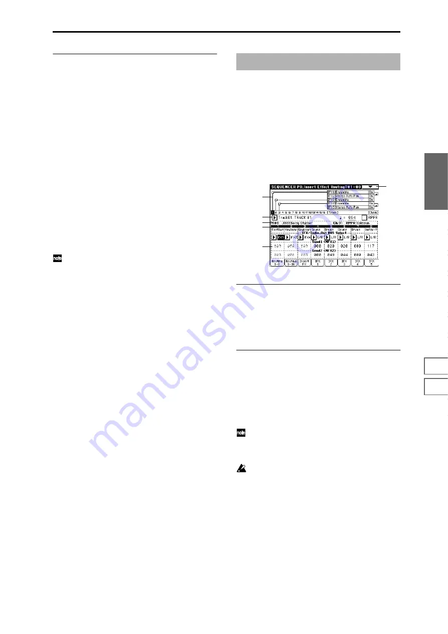
Here you can make insert effect settings, and specify the bus
etc. for the program used by each track 1–16.
☞
For details on insert effects, refer to p.205 “8. Effect
Guide.”
8–1: Routing 1–8
(Routing T01–08)
8–2: Routing 9–16
(Routing T09–16)
Specify the bus to which the program oscillator(s) of each
track 1–16 will be sent. You can also set the amount of signal
that will be sent to the master effects.
8–1a: Routing Map
This shows the status of the insert effects: the insert effect
routing, the names of the selected effects, the on/off status,
and chaining.
The effect type, on/off, and chain settings can be made in
the Insert FX page (8–2).
8–1(2)b: BUS Select (IFX/Indiv.Out BUS Select),
Send1 (MFX1), Send2 (MFX2)
BUS Select (IFX/Indiv.Out BUS Select)
[DKit, L/R,
IFX1...5, 1, 2, 3(Tube), 4(Tube), 1/2, 3/4(Tube), Off]
These settings specify the bus to which the program oscilla-
tor(s) of each track 1–16 will be sent.
The status of the settings can also be viewed in the “Routing
Map” (
☞
Combination P8–1: Routing).
If you want to insert Valve Force into the program oscil-
lator output of a track, set this parameter to 3/4 (Tube),
3 (Tube)
, or 4 (Tube). Set the Valve Force “Placement”
(9–5a) to Insert.
When 1/2 or 3/4(Tube) are selected, the program of the
corresponding track 1–16 will be output in stereo from
AUDIO OUTPUT (INDIVIDUAL) 1 and 2 or 3 and 4. If
you use CC#10 (pan) or AMS to control the panning of
the program oscillator, the new pan setting will be
applied at the next note-on. Unlike the case when you
select L/R to output the sound from (MAIN) L/MONO
and R, the pan of a sounding note cannot be varied in
realtime.
If you wish to vary the pan of a sounding note in real-
time, and output the result from AUDIO OUTPUT
(INDIVIDUAL) 1 and 2 or 3 and 4, set “BUS Select” to
IFX1
(or IFX2–IFX5), select 000: No Effect for “IFX1”
(or IFX2–IFX5) (8–3), and select either 1/2 or 3/4(Tube)
for “BUS Select” (8–3) after the signal passes through
IFX.
Sequencer P8: Insert Effect
8–1
5–1b
0–1b
0–3a
8–1b
8–1a
Summary of Contents for TRITON Extreme
Page 1: ...2 E ...
Page 11: ...xii ...
Page 111: ...100 9 5 Page Menu Command 0 1A 0 1I 0 1J Program 9 5A ...
Page 185: ...174 ...
Page 215: ...204 ...
Page 281: ...270 ...
Page 349: ...338 ...
Page 350: ...339 ...
Page 351: ...340 ...
Page 352: ...341 ...
Page 353: ...342 ...


