background image

29

KOSPEL S.A.

ul. Olchowa 1

75-136 Koszalin
tel. 94 346 38 08

serwis: 94 317 05 65

e-mail: serwis@kospel.pl

www.kospel.pl

Compiled:       Łukasz Pelech 


     Paweł Wojtanowski


     Przemysław Biegański

Summary of Contents for ECKO.TM

Page 1: ...1 KOSPEL S A KOSZALIN ul Olchowa 1 SERVICE MANUAL EKCO T ECKO TM 17 11 2020 ...

Page 2: ...4a Front view of the control panel 11 Pic 4b Back view of the control panel 11 4 1 Control panel PSK M2 EKCO TM extended menu 12 Tab 2 Extended menu 12 4 2 Failure modes of PSK P4 control panel 13 Tab 3 Failures 13 5 ZIO 23 board EKCO T 14 Pic 5 Description of ZIO 23 14 6 Connection of control panel PSK P4 and ZIO 23 board 15 Pic 6 Connection of control panel PSK P4 15 7 ZIO 24 board EKCO TM 16 Pi...

Page 3: ...he heating system Boilers supply the hydraulic clutch 21 Pic 14 Additional electrical connection for boilers in cascade 22 13 Wiring diagram 23 Pic 15 Wiring diagram 23 14 Pump Grundfos UPM3 Flex AS 24 Pic 16 De block the pump 24 Tab 5 Settings view 24 Tab 6 Alarm status 24 14 1 Pump Wilo Yonos Para 25 Pic 17 Settings via operating knob 25 14 2 Pump Wilo Yonos Para alarm status 26 Tab 7 Alarm stat...

Page 4: ...Service manual EKCO T EKCO TM 4 1 Exterior view of boilers Pic 1a EKCO T boiler 3 01205 17 01219 23 00035 32 4 01214 ...

Page 5: ...5 Pic 1b EKCO TM boiler 5 01216 19 01220 23 00035 32 6 01217 ...

Page 6: ...Service manual EKCO T EKCO TM 6 2 Construction of boilers Pic 2a Construction of the boiler EKCO T ...

Page 7: ...7 Pic 2bConstruction of the boiler EKCO TM ...

Page 8: ...Service manual EKCO T EKCO TM 8 3 Control panel PSK P4 EKCO T 0 1 0 Pic 3a Front view of the control panel Pic 3bBack view of the control panel ...

Page 9: ...rks in winter mode t UP o EJTQMBZJOH UIF PVUMFU UFNQFSBUVSF GSPN UIF CPJMFS POMZ t U P o EJTQMBZJOH UIF PVUMFU UFNQFSBUVSF GSPN UIF CPJMFS BOE GSPN MFGU BOE SJHIU IFBUJOH CPY operation in cascade connection t S JOEFQFOEFOU CPJMFS PQFSBUJPO UIF CPJMFS JT OPU SFDPHOJTFE CZ NBTUFS TFOTPS t S DBTDBEF PQFSBUJPO number of boiler that works in cascade This parameter can only be changed when the boiler is...

Page 10: ...ace the servo of valve ZIO 23 failure Replace ZIO 23 board DHW temperature is too low The boiler is heating only the heating system 5IF JOEJDBUPS JT Pò The DHWT thermostat or DHWT electronic Sensor DS 1820 failure Replace DHWT thermostat or electronic sensor DS 1820 ZIO 23 failure Replace ZIO 23 board Too low DHWT temperature settings Set the higher temperature on the DHWT thermostat or rise the D...

Page 11: ...panel 1 Display 2 Buttons 3 ZIO 24 connection point 4 Cascade connection socket 5 ZIO 24 connection point 6 Supply temperature sensor connection point left heating box 7 Return temperature sensor connection point 8 Supply temperature sensor connection point right heating box 9 Flow sensor connection point ...

Page 12: ... t W S Y S U c P S a U _ V T S s Y S S e g g L M R Z y U R V R S Z W U s W S R X S Y Z W V Y S _ W S S _ T U Y V U W c d P e g L M O S _ T U Y V U W W S R X S Y Z W V Y S U W S Z S _ _ V W T _ _ Y S _ Y Z U a V Y S c d P e h g L M Ä À Å Æ Æ À À Ç _ X S Y Z W U _ b È W S Z S _ W S W Y S S q Z t Z a S _ V W a S W _ U a a Z W U _ c Z a S _ X S _ Y a _ S W _ _ É V U Ê e Z T _ V W a S W W S R X S Y Z W...

Page 13: ... the screw to rotate the rotor Replace pump Flow sensor failure Replace flow sensor The supply temperature is too low Heating box failure Check or replace heating box Faults display view shows possible failures flow failure outdoor room temperature sensor failure inlet outlet boiler sensor failure The controller enables failure detection and identification short circuit or sensor disconnection mis...

Page 14: ... 1820 WZ connection point of DHWT thermostat RP room thermostat connection point or jumper NA master appliance connection point or jumper ZTD connection point of three way valve ZM power module I2C PSK P4 cable X NA PSK P4 cable F1 1 A fuse pump protection D S control panel communication indicator D Z DHW tank heating indicator D P pump operation indicator ...

Page 15: ...15 6 Connection of control panel PSK P4 and ZIO 23 board Pic 6 Connection of control panel PSK P4 ...

Page 16: ...r floor heating or second heating circuit supply connection 11 POMPA 2 second circuit pump supply connection 12 POMPA CWU DHW pump supply connection 13 ZAS three way switching valve DHW Cylinder supply connection 14 POMPA C H pump supply connection 15 ZIO 24 board supply connection 16 ZM power boards connection point 17 pump operation indicator 18 230 volt on LB connection indicator three way swit...

Page 17: ...17 8 Connection of control panel PSK M2 and ZIO 24 board Pic 8 ZIO 24 board connection 01 01 2 ...

Page 18: ...4 0 5 6 7 8 9 2 3 0 4 0 5 5 5 3 0 9 0 35 5 0 4 2 4 2 2 2 3 0 4 0 5 9 9 A B C 0 4 3 4 1 2 2 3 0 4 0 5 D E F G H I J K K L M K K J M N O P Q J M O P L M O M Q L J O R S K K D E F G H I J T K L M K L J M S O U Q M P O J U O S Q N O J D E F G H I S M K L M K M J M L O M Q M J O S L P O L Q L U O N D E F G H I S U K L M K J T L U O T Q M K O S L N O T Q M L O R Tab 4 Electric parameters of heating box ...

Page 19: ...19 10 Connection diagram of heating box Pic 10Connection diagram of heating box ZIO 23 or ZIO 24 ...

Page 20: ...Pic 11a Connection diagram for the DHW tank EKCO T Thermostat ZAS N LA LB ZIO24 PSK M ZM W N U POMPA U N POMPA CWU U N PE POMPA 2 PE N U ZTM N U U I2C STATUS RP WZ Tzas WZ RP Tpok Tzew Tco2 NA white yellow black brown blue Pic 11b Connection diagram for the DHW tank EKCO TM black brown blue ...

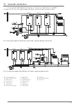
Page 21: ...upply the hydraulic clutch CTP room temperature sensor F magnetic filter ZM mixing valve CTZ outdoor temperature sensor SH hydraulic clutch ZTD three way switching valve TZ DHWT thermostat ZP straight through valve ZO air vent valve NW expansion vessel ZT thermostatic valve RW expansion pipe ZZ check valve PO circulation pump ZR regulating valve PO additional circulation pump ZU discharge valve ...

Page 22: ... is a number that inform about the boiler in the network connection Each boiler has its own address The address number can not be higher than number of slave boilers For example if you build boilers cascade system with the EKCO TM as a master appliance and three other boilers as a slave appliances the slave appliance should have the following addresses A1 A2 and A3 The boilers must be connected in...

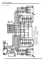
Page 23: ...wer supply connector F1 F2 WT 3 safety cut out XP1 XP2 terminal strips ZM1 ZM2 power boards ZG1 ZG2 heating boxes M1 pump ZIO I O board PSK P4 PSK M2 control panel T1 return temperature sensor T2 supply temperature sensor Q flow sensor K1 front cover ...

Page 24: ...er out of heating season and simultaneous noncompliance with the recommendation to leave the driver in this period in a parking mode please restore proper movement of the impeller To do this please use PH2 screwdriver press and turn the screw left located in the middle of the front panel of the pump The pump impeller should be unblocked then 0 1 2 3 ...

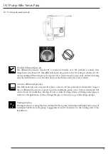
Page 25: ... valves are reduced Constant differential pressure The differential pressure setpoint H is kept constant over the permitted volume flow range at the set differential pressure setpoint up to the maximum pump curve Wilo recommends this control mode for underfloor heating circuits or older heating systems with large sized pipes as well as for all applications with no changeable pipe system curve e g ...

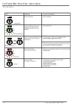
Page 26: ...Service manual EKCO T EKCO TM 26 14 2 Pump Wilo Yonos Para alarm status Tab 7 Alarm status ...

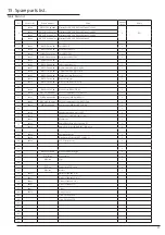
Page 27: ...pipe 1 14 15 01204 EKCO T 05 03 00 Power board EKCO T TM 2 16 01010 EKCO L 14 00 00a ZIO 23 connection board EKCO T 1 17 01219 PSK P4 00 00 00 04 Control panel PSK P4 EKCO T 1 18 01041 EKCO M 11 00 00 ZIO 24 connection board EKCO TM 1 19 01220 PSK M2 00 00 00 Control panel PSK M2 EKCO TM 1 20 1 21 02346 Supply temperature sensor NTC 1 22 01339 Flow sensor with inlet temp sensore 1 23 00035 Manomet...

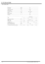
Page 28: ...n pressure MPa 0 1 Outflowing water temp C 40 85 Max water temp C 100 Overall dimensions mm 815 x 503 x 197 Weight kg 29 Water connection G1 Safety class IP 21 81 4 107 2 0 35 14 0 4 60 4 4 522 4 53 2 4 522 4 0 4 7 2 3 3 4 0 0 4 7 2 3 3 4 0 9 5 07 4702 1 Tab 9 Technical data ...

Page 29: ...29 KOSPEL S A ul Olchowa 1 75 136 Koszalin tel 94 346 38 08 serwis 94 317 05 65 e mail serwis kospel pl www kospel pl Compiled Łukasz Pelech Paweł Wojtanowski Przemysław Biegański ...

Page 30: ... LQ WKH FLUFXLW LV WRR ORZ PHGLXP ÀRZ UDWH UHDGLQJ HUURU ZDLW XQWLO WKH VWDUW XS SURFHGXUH LV QLVKHG V PSWRP UHDVRQ DFWLRQ RQWURO SDQHO LQGLFDWRUV DUH RII ODFN RI ERLOHU SRZHU VXSSO FKHFN SDUDPHWHUV RI WKH SRZHU QHWZRUN DQG IXVHV FRQWDFW WKH VHOOHU LQGLFDWRU ÀLFNHUV SXPS LV EORFNHG XQEORFN WKH SXPS E XQVFUHZ WKH VFUHZ RQ SXPS KRXV LQJ DQG PRYH WKH SXPS URWRU PDQXDOO PHGLXP GRHVQ W FLUFXODWH WKURXJ...

Reviews: