background image

Service manual  EKCO.L2N

16


Press 

 until only indicator 

 is illuminated.  The LED display shows temperature of water in DHW 

cylinder.  Press 

  or 

  until  the  desired  temperature  setting  is  achieved.  Min.  temperature  is  30  C.  Max 

temperature depends on the return temperature and is less than  for 5 degrees.Set “0” value to disable heating 

of DHW cylinder (

 indicator is blinking) . 

Press once 

 button when control panel shows overall view to set summer mode.


3.e. Service menu:


For service settings switch the control panel to standby mode (hold button 

 for 3 seconds) then hold 

the 

  and  press 

.  To  select  parameter  press 

,    buttons 

  or 

  enable  you  to  change  the  value, 

consecutively:

1. Boiler power (value on digital display 11). Value of this parameter must be same like a power of heating box.
2. Working mode of pump
 

„Pa” – automatic work mode


„Pr” – manual, continous work mode

3.. Number of active heating elements 
 

„G3” – three heating elements


„G2” – two heating elements


„G1” – one heating element 

4. Boiler work mode
 

„no” – normal mode for central heating (temperature range 

20 – 85°C)


„Po” –floor heating mode (temperature range  

20 – 60°

C)

5. Load temperature of DHW cylinder (value on digital display 11, indicators 

°C 

and


 are illuminated)

- temperature range  

50 – 85°C

- Value 

"0"

 -  DHW cylinder disable

Set 

“0”

 when boiler works without DHW cylinder.

6.Type of  DHW sensor.
 

ti – temperature sensor NTC (WE-019)


tE – contact thermostat

7. Pressure lock function (bar indicator on)


0

” – inactive function


1

” - active function - heat and pump will be blocked below pressure 0,6 bar

8. Boiler work mode


A0

” – single mode


A1

” do „

A9

” – cascade mode ( Each boiler must have a different address „

A

9. Type of flow sensor (l/min indicator on)


1

” - Flow sensor HubaControl


2

” - Flow sensor Kospel

10. Work-time counter (value displayed on indicator 11) .
Counter display shows figures (without leading zeros) starting from the most important (interrupt every 1/2 

second), the display will turn off (for 2 seconds) when the least important figure is shown. Example if display 

displayed number in order 1..2..9........1..2..9. That mean boiler has been working for 129 hours.
 

Press and hold the @ button to exit and record the settings 

.

Summary of Contents for EKCO.L2N

Page 1: ...1 KOSPEL S A KOSZALIN ul Ol cho wa 1 SERVICE MANUAL EKCO L2N EKCO L2Np EKCO L2NF 14 03 2016...

Page 2: ...C H temperature settings 15 3 d D H W cylinder settings 15 3 e Service menu 16 3 1 Connecting of external devices to the control panel PSK P5 17 Pic 13 Connecting of external devices 17 4 Heating box...

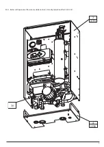
Page 3: ...3 5 01181 3 01179 4 01180 17 01182 1 Exterior view of boilers Pic 1 Exterior view 14 01168 Part number in table of parts Service code...

Page 4: ...Service manual EKCO L2N 4 1 1 Exterior view open case 39 3 01179 4 01180 Pic 2 Boiler with open case flow sensor Kospel date of production before 29 03 2011...

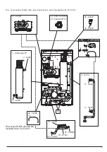
Page 5: ...5 Pic 3 Boiler with open case flow sensor Huba Control date of production after 29 03 2011 39 3 01179 4 01180...

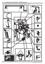
Page 6: ...w sensor Kospel date of production before 29 03 2011 2 Construction of boilers 25 00001 35 00253 27 00516 100 C 00489 o 75 C o 21 00791 Tout 20 00790 Tin 17 01182 9 01174 1 Ta 18 ble on page 16 01183...

Page 7: ...er 29 03 2011 25 00001 35 00253 27 00516 100 C 00489 75 C 27 20 00790 Tin 17 01182 9 01174 1 Table page 18 16 01183 37 00882 37 00882 37 00882 37 00882 37 00882 32 34 01270 15 01331 Tout 21 00791 Tout...

Page 8: ...re 29 03 2011 28 Table page 27 38 00647 8 01173 Tout Tin 38 00647 37 00882 10 01175 37 00882 30 01294 37 00882 12 01177 38 00647 37 00882 23 01194 24 01195 37 00882 11 01176 36 00255 37 00882 9 01174...

Page 9: ...0882 30 01294 37 00882 23 01194 24 01195 37 00882 11 01176 9 01174 26 00144 36 00255 18 01212 lub 01339 after 13 07 2011 20 00790 22 01541 after 11 08 2014 34 01270 37 00882 37 00882 32 16 01183 37 00...

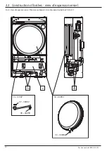
Page 10: ...nual EKCO L2N 10 2 2 Construction of boilers view of expansion vessel 14 00853 13 01187 37 00882 36 00255 37 00882 6 32 31 Pic 8 View of expansion vessel flow sensor Kospel date of production before 2...

Page 11: ...11 Pic 9 View of expansion vessel flow sensor Huba Control date of production after 29 03 2011 14 00853 37 00882 6 32 18...

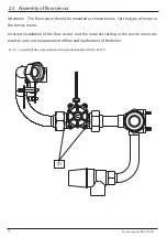
Page 12: ...date of production after 29 03 2011 Attention The flow sensor should be mounted as shown below Set the type of sensor in the service menu Incorrect installation of the flow sensor and the incorrect s...

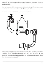
Page 13: ...the flow sensor and the incorrect setting in the service menu can result to incorrect measurement of flow and malfunction of the boiler Attention On 13 07 2011 was change in build construction Flow se...

Page 14: ...k out the following working parameters by pressing the button A display shows in sequence medium temp setting D and M indicators are on inlet temp D and K indicators are on outlet temp D and L indicat...

Page 15: ...free voltage entry room thermostat connection point Work without room thermostat need to use a jumper Tzas DHW temperature sensor or DHW thermostat connection Set type of sensor in service menu or tak...

Page 16: ...ment 4 Boiler work mode no normal mode for central heating temperature range 20 85 C Po floor heating mode temperature range 20 60 C 5 Load temperature of DHW cylinder value on digital display 11 indi...

Page 17: ...c 13 Connecting of external devices NA RP Tzas Q Twej Twyj Ci ZM Pompa ZTD N L N L N LA LB Za NTC Sensor Thermostat PROG 0 6 12 18 24 0 c Ni Po Wt r Cz Pt So COM NO NC Auraton 2005 lub NO COM BK NC LA...

Page 18: ...t passing through the heating element A U Working voltage of the heating elements V EKCO L2NF 4 01184 wyk 001 3 37 1 40 9 5 6 6 2 230 EKCO L2NF 6 01186 wyk 003 3 24 8 28 6 8 0 9 3 EKCO L2N 4 01184 wyk...

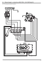
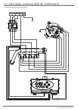
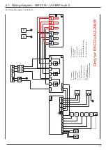
Page 19: ...connection 400V 3N 12 24 kW wyk I Pic 15 Power board connection 12 24 kW 3N Power supply 400V 3N U V W N Ground NA RP Tzas Q Twej Twyj Ci ZM Pompa ZTD N L N L N LA LB Za H e 1 H e 2 H e 3 red blue L3...

Page 20: ...2 Power board connection 400V 3N 4 8 kW wyk II Pic 16 Power board connection 4 8 kW 3N Power supply 400V 3N U V W N Ground NA RP Tzas Q Twej Twyj Ci ZM Pompa ZTD N L N L N LA LB Za H e 1 H e 2 H e 3...

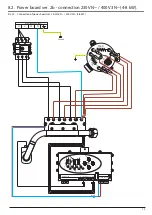
Page 21: ...8 kW wyk III ver 1 Pic 17 Power board connection 4 8 kW N ver 1 date of production before 17 11 2010 Power supply 230V N U N Ground NA RP Tzas Q Twej Twyj Ci ZM Pompa ZTD N L N L N LA LB Za H e 1 H e...

Page 22: ...Ground NA RP Tzas Q Twej Twyj Ci ZM Pompa ZTD N L N L N LA LB Za H e 1 H e 2 H e 3 red blue L3 G3 L2 G2 L1 G1 N V W The second version allows you to configure the installation for one or three phase p...

Page 23: ...BK U V W N Tzas NTC LA LB ZTD N F1 T1 Return temperature sensor MSK MSK board ZM power board Q flow sensor ZG heating box Kp front cover M1 circulating pump XP terminal strip LPE F1 WT 3 cut out T2 fl...

Page 24: ...WT 3 N PE Power supply 400v 3N U V W N Tzas NTC LA LB ZTD N T1 return temperature sensor MSK MSK board ZM power board Q flow sensor ZG heating box Kp front cover M1 circulating pump XP terminal strip...

Page 25: ...P L Zas N U V W WT 3 N PE U N Tzas NTC LA LB ZTD N Power supply 230V N BK RP NC NC T1 return temperature sensor MSK MSK board ZM power board Q flow sensor ZG heating box Kp front cover M1 circulating...

Page 26: ...M power board Q flow sensor ZG heating box Kp front cover M1 circulating pump XP terminal strip LPE F1 WT 3 cut out T2 flow temperature sensor Kd bottom cover BK boiler lock always closed RP room ther...

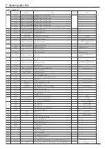
Page 27: ...pipe 16 01183 PCA ZM 60 02 Power board EKCO L2 1 17 01182 PSK P5 00 00 00 Control panel PSK P5 1 01338 Control panel PSK P5 EHC 1 18 01212 Flow sensor DN15 200 915101 EKCO T TM 1 19 01229 Flow sensor...

Page 28: ...Power board ver 2b connection 400V 3N 12 24 kW Power supply 230 400V U N Ground NA RP Tzas Q Twej Twyj Ci ZM Pompa ZTD N L N L N LA LB Za H e 1 H e 2 H e 3 red blue L3 G3 L2 G2 L1 G1 N V W Pic 23 Conn...

Page 29: ...ction 230V N 400V 3N 4 8 kW Power supply 230 400V U N Ground NA RP Tzas Q Twej Twyj Ci ZM Pompa ZTD N L N L N LA LB Za H e 1 H e 2 H e 3 red blue L3 G3 L2 G2 L1 G1 N V W Pic 24 Connection of power boa...

Reviews: