background image

51

50

9.3 CHECKS AND ACTIONS BEFORE COMMISSIONING

Damage to the loader or attachment (optional equipment) can lead to unpredictable and dangerous situations. If you notice 
any damage or other fault of the loader or attachment during the following checks, the loader must not be used until all the 
defects have been removed.


Do not remove, disable or turn off safety devices or switches.


Do not change predefined setpoints.


Do not use the loader until it has been properly repaired.

Before putting the loader into operation, make sure that its safe operation is guaranteed:


The boom and bucket arms must not be visibly damaged.


The locking device of the attachment must not be damaged or deformed.


Any other accessories as well must not show any visible damage (such as bends, cracks, significant wear).


The pins must be properly lubricated and inspected.


The space under the loader must be checked for leaks of working fluids.


The protective grilles (optional equipment) and the driver’s protective roof must not be damaged and must be  


roperly fastened.


The attachment (optional equipment) must be correctly fastened and must operate in accordance with the operat- 


ing instructions.


All information labels must be affixed in place and legible. Damaged or missing labels must be replaced according 


to indications in the chapter "Identification Points".


All warning devices (such as the warning horn) must be in perfect condition and fully functional.


Make sure to check for damage and leaks in visible parts of the hydraulic system and the hydraulic oil tank.  


Damaged hoses must be replaced.


The batteries must be located securely in the battery compartment.


The battery plug must be inspected for damage (e.g. cracks, fissures or housing deformation, bending or damage  


to contacts). If necessary, the battery plug must be replaced in an authorized service center.


The battery cover must be securely closed.


The battery lock must not be damaged or deformed.


The base frame of the battery, the battery compartment and the battery cover must not be damaged or deformed.


The service covers must be closed and the cabin safety locks secured.


The cabin steps must be clean and ice-free.


The cabin locks and their locking pins must be secured before using the machine.


All glass surfaces (such as the front windscreen) must be clean and ice-free.


Depending on the tyres, the loader can be equipped with an antistatic belt. The antistatic belt must not be damaged.  


Further it must be clean and long enough to touch the ground.


Damage to or other defects of the loader including attachment (special equipment) must be reported immediately  


to the operator do that the fault can be rectified by the same.
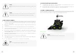
10. OPERATION

10.1 OPTIMUM OPERATING CONDITIONS TO CONSERVE THE BATTERY CAPACITY
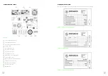
10.1.1 BATTERY CAPACITY INDICATOR: THE DISPLAY BACKLIGHT

When working with the Elise 900 loader, it is very important to monitor the machine load or the power intake from the loader 
battery. For this, the power intake indicator is used in the Kovaco application on the phone. 

10.1.2 RECOMMENDED SPEEDS

When working with the loader with the basic shovel, we recommend setting the machine’s travel speed to 2 and hydraulic 
speed to 3. For fine handling of heavy objects when loading or unloading, the recommended settings are travel speed 1 
and hydraulic speed 1. Travel speed 1 and hydraulic speed 1 also are recommended for connecting attachments. For other 
types of work with the loader, the settings must be done and adjusted according to the type of task at hand. As a rule when 
working with the loader, the lower the speed, the more substantial savings on battery capacity.

10.1.3 DRIVING STYLE

The battery capacity is significantly affected also by the actual driving style. As far as the situation allows it, it is recom-
mended to turn with the machine in a style around the entire radius, that is, with the wheels on one side of the loader not 
moving, or moving at low speed, and rotating on the other side of the machine. In this way, the loader turns economically. 
It is uneconomical to turn around the axis, which is with the wheels on each side moving in the opposite direction from the 
other side. This will result in a sharp drop in battery capacity. 
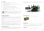
10.1.4 SURFACE

The surface on which the loader operates also greatly affects the battery capacity. The loader has rough-terrain tyres 
mounted as a factory standard, specifically tyres with a sparse and high tread pattern. However, this tyre is not suitable  
for tarmac or concrete as it is soft, has great rolling resistance and it slips. 

Where the machine is expected to operate mostly on paved surfaces such as tarmac or concrete, it is recommended  
to equip the loader with tyres for paved surfaces to avoid heavy draw on the battery and severe tyre wear. 

10.1.5 TURNING OFF BUCKET LEVELLING

Moderate savings on battery capacity can also be obtained by disabling bucket levelling. This function mainly is used  
for working at more elevated heights. This means working above the vehicle operator’s cabin, where visibility of the work 
device is impaired. The higher draw on the battery is due to the fact that the hydraulic pump has to run at a higher output 
in order to be able to supply oil to two sections of the distributor simultaneously. Therefore, when levelling is on, the boom 
speed also is slightly lower. 

10.1.6 HEATING AND AIR-CONDITIONING

The use of heating and air-conditioning also has a significant effect on the battery capacity. For loaders with an internal com-
bustion engine, the use of air-conditioning results in an increase in the machine power consumption by up to 10%. Similarly, 
it also reduces the battery capacity of the electric machine.

!

Warning

Risk of damage to components!

A deformed or damaged battery plug may cause overheating and subsequent damage.

Summary of Contents for Elise900

Page 1: ...Elise900 User Manual for Operation and Maintenance ...

Page 2: ...KOVACO Electric a s 1st edition 2020 ...

Page 3: ...NVIRONMENTAL IMPACTS 19 3 1 PACKAGING 19 3 2 DISPOSAL OF COMPONENTS AND BATTERIES 19 4 USE OF THE SKID STEER LOADER 19 4 1 PROPER USE 19 4 2 CORRECT USE WHEN TOWING 19 4 3 INAPPROPRIATE USE 20 4 4 PLACE OF USE 20 4 5 PARKING AT TEMPERATURES BELOW 10 C 20 4 6 USE OF WORK PLATFORMS 20 4 7 RESIDUAL RISK 21 4 8 STABILITY 22 4 9 SPECIAL RISKS RELATED TO THE USE OF THE LOADER AND ITS ATTACHMENTS 22 5 OV...

Page 4: ...TION AND PUTTING THE LOADER INTO OPERATION 62 10 9 CHANGING THE FLOW RATE OF HYDRAULIC OIL 63 10 10 WORK LIGHTS 63 10 11 ROAD LIGHTS 63 10 12 BEACON 64 10 13 DEACTIVATING THE BOOM AND BUCKET CONTROLS 64 10 14 FRONT WINDSCREEN CLEANING 64 6 3 BASIC SAFETY RULES FOR OPERATION 25 6 3 1 INSURANCE COVERAGE ON A CONSTRUCTION SITE 25 6 3 2 ALTERATIONS AND MODIFICATIONS 25 6 3 3 CHANGES TO THE DRIVER S PR...

Page 5: ...E 73 17 2 CORRELATION TABLES FOR OILS AND LUBRICATING GREASES 75 17 2 1 HYDRAULIC TANK 75 17 2 2 TRANSMISSION GEARS 75 17 2 3 ALL GREASE LUBRICATED POINTS 75 17 3 DESCRIPTION OF MAINTENANCE ACTIVITIES 76 17 3 1 OIL CHANGE IN THE HYDRAULIC SYSTEM 76 17 3 2 MAINTENANCE OF HYDRAULIC CYLINDERS 76 17 3 3 CHECKING AND INFLATING TYRES 76 17 3 4 CHECKING AND TIGHTENING NUTS 76 17 3 5 CHANGING OIL IN GEARB...

Page 6: ...0 MANUFACTURER S ADDRESS AND CONTACT DETAILS KOVACO Electric a s U Hellady 4 140 00 Prague 4 Czech Republic Company ID 089 00 213 Tax ID CZ 089 00 213 www kovacoe lectric com e mail info kovacoelectric com ...

Page 7: ...e using the loader verify that the vehicle operator Is informed about the correct use of the loader and its safe operation Has read and understood the operating instructions for the loader at hand Has read and understood ALL the safety labels on the loader Is actually a person that works in the operating zone Has familiarized themselves with operating the loader controls in a safe and empty area b...

Page 8: ...affect the protective properties of this structure and invalidate its certification Do not weld anything on or drill any holes into the structure Consult the manufacturer about the pos sibilities for modifications to the protective structure so that the certificate is not revoked 1 2 CE MARKING The manufacturer uses the CE mark to demonstrate the conformity of the skid steer loader with the standa...

Page 9: ...thorized service center for technical support for your skid steer loader 2 2 COPYRIGHT AND TRADEMARK RIGHTS This manual including its parts may not be reproduced translated or provided to third parties without the express written consent of the manufacturer 2 3 EXPLANATION OF THE SYMBOLS AND ABBREVIATIONS USED Danger Denotes procedures that must be strictly observed to avoid Dangers to life Explos...

Page 10: ...Classes 1 and 2 according to ČSN 73 3050 using specifically designated attachments You will find the classification of rocks at the end of the manual The loader may only be used for its designated purpose as specified and described in these operating instructions If the loader is to be used for any purpose other than specified in the operating instructions the approval of the manufac turer and if ...

Page 11: ...ith all standards and regulations risks cannot be completely excluded when using the loader The components of the loader and of the entire system meet current safety requirements Even when the loader is used exclusively for its intended purpose and all instructions are followed certain residual risks cannot be ruled out Such residual risks cannot be completely excluded even outside the narrow risk...

Page 12: ...d safety in the given country of operation the operator is obliged to determine and assess operating risks and set the necessary measures to ensure occupational health and safety of staff The operator must therefore draw up an appropriate operating manual and provide it to the driver An authorized person must be appointed 6 SAFETY 6 1 DEFINITIONS OF TERMS 6 1 1 OPERATOR The operator is a natural p...

Page 13: ...specified in regulations or in these operating instructions and the loader must be mod ified or retrofitted please note that any alteration of the loader design may affect its stability and performance which may result in various accidents Therefore contact your service center before making any modifications Without the manufacturer s consent it is prohibited to make changes that among other thing...

Page 14: ...or at a distance required by applicable legal requirements A failure to observe this provision may result in interfering with explosive blasting operations which can result in serious injury or death 6 3 3 CHANGES TO THE DRIVER S PROTECTIVE ROOF AND ROOF LOAD Do not weld on the driver s protective roof Do not drill on the driver s protective roof When welding or drilling on the driver s protective...

Page 15: ...electromagnetic interference Medical devices such as pacemakers or hearing aids may not function properly during the loader operation Check with your doctor or medical device manufacturer to make sure that it is sufficiently protected against electromagnetic interference Warning The loader may overturn there is a risk of accident A failure to follow these instructions and information may result in...

Page 16: ...n handling liquids Make sure that these liquids do not get into contact with hot parts of the machine and the environment Avoid contact of these liquids with skin Do not inhale spray liquid Leakage of compressed fluids escaping under high pressure from the hydraulic system is extremely dangerous In the event of such an injury seek medical attention immediately To prevent injuries use appropriate p...

Page 17: ...risk of fire The loader must be cleaned as needed to prevent such buildup Do not use the loader where electric arcs sparks or hot parts may come into contact with flammable substances or explo sive atmospheres Inspect all electrical wires and connections for damage Keep the battery terminals clean and screwed tight Repair or re place any damaged component Inspect fuel and hydraulic pipes hoses and...

Page 18: ...not allowed to use any lubricants other than those specified in these maintenance instructions Mixing individ ual lubricants is prohibited Contact an authorized service center to have more complex repairs carried out by them Danger There is a risk of falling when working on high parts of the loader Warning The maximum load capacity of the machine 900 kg can only be used on a paved and level surfac...

Page 19: ... the loader We ask that you familiarize yourself with their contents before starting any work In the basic version the loader can work in the WT climate zone according to ČSN 038900 with the range of working temperatures adjusted to 15 to 35 C according to ČSN ISO 7131 Earth moving machines Loaders For working in other climate zones the loader must be modified subject to arrangement between the su...

Page 20: ...rs 1 back to the orig inal horizontal position Picture 8 quick clamp in secured position Picture 7 Picture 8 7 7 ELECTRICAL INSTALLATIONS The electric drive of the loader is provided with a voltage of 96 V all other appliances are in the 12 V version The power source are batteries located in the rear part of the frame The appliances are protected by fuses To control the appliances and for monitori...

Page 21: ...electrical switch If the seat is not loaded the machine controls remain switched off The front windscreen is cleaned with a washer and electric wiper Warning Tilting the cabin To tilt the cabin the safety locks in the rear cabin consoles must be unlocked Picture 9 Boom lock 1 safety strut 8 VIEWS 8 1 OUTSIDE VIEW OF THE LOADER Picture 10 Cabin Door Boom Frame Basic shovel Transmission Wheel Hydrau...

Page 22: ...er Seat Front windscreen washer reservoir Heating controller Reversing camera monitor on the front windscreen Right control lever handle Reserve button Full oil flow lock button Attachment button f2 Attachment button f1 Reserve button Armrest Picture 11 8 3 VIEW OF RIGHT CONTROL LEVER Picture 12 1 1 2 2 3 3 4 4 5 5 6 6 7 7 8 9 10 ...

Page 23: ...cator Active road lights indicator Active motorway lights indicator Menu to return to landing page Indicator of device connected to the application Active bucket balancing Active beacon indicator Active warning triangle indicator Travel speed selection Selected travel speed level Travel speed selection locked Right turn indicator Battery status indicator Name designation of machine The individual ...

Page 24: ...manufacturer s label Chassis manufacturer s label Cabin manufacturer s label Lubrication schedule and maintenance Hydraulic tank No entry warning sign Information on controls Information on controls Tyre inflation pressure Attachment point for lifting device Cabin heating controls Warning read the operating instructions Battery disconnection point Maximum speed indication Emergency exit sign Maxim...

Page 25: ...displays Picture 24 2 Drag down from the top of the screen to see the phone settings such as the Bluetooth icon Picture 25 3 Press and hold the Bluetooth icon for about 2 seconds until the Bluetooth menu appears on the display If Bluetooth is turned off a screen will appear where you need to turn Bluetooth on Picture 26 4 Bluetooth is activated by dragging the button to the right Picture 27 5 When...

Page 26: ...PLAY BACKLIGHT When working with the Elise 900 loader it is very important to monitor the machine load or the power intake from the loader battery For this the power intake indicator is used in the Kovaco application on the phone 10 1 2 RECOMMENDED SPEEDS When working with the loader with the basic shovel we recommend setting the machine s travel speed to 2 and hydraulic speed to 3 For fine handli...

Page 27: ...ghtwillbe flashing during the entire charging process If you want to stop charging press the green button again After the initial charging the yellow FINAL CHARGING light will illuminate The electric timer starts counting down the last 3 hours of final charging When the last charging stage is completed the charger switches off automatically and the green indicator light indicates END OF CHARGING A...

Page 28: ...h a different type of tyres from those approved by the loader manufacturer or with tyres from another manufacturer you must first obtain consent from the loader manufacturer Make sure that the surface of the footwell is not slippery Do not jump into or out of the loader Make sure you always hold on firmly to the loader Do not wear jewellery at work Do not wear loose work clothing Danger Beware of ...

Page 29: ...read 1 4 Place the right foot on the arm tread 2 5 Grip the handrail 5 with your right hand and at the same time hold the handrail 5 for support with your left hand 6 Get into the loader and seat yourself in the driver s seat Exit the loader in the reverse order of steps 10 6 ADJUSTING THE DRIVER S SEAT GRANT ST PLUS Do not adjust the driver s seat or backrest while driving Adjust the driver s sea...

Page 30: ...adjusted to the weight of your body It will have a positive effect on your back and help protect your health The seat suspension is adjusted with lever 3 Picture 37 Picture 37 Picture 38 Picture 39 Picture 40 10 6 4 ADJUSTING THE LUMBAR SUPPORT The lumbar support can be adjusted to suit the shape of the spe cific driver s spine When adjusting the lumbar support you move the convex support cushion ...

Page 31: ...cture 45 Safety ramp in closed position Picture 47 The armrests must be at the same height for the correct position and securing of the safety ramp Picture 49 Incorrect position of the vehicle operator Picture 50 For closing the safety ramp correctly make sure that the driver s legs are positioned evenly side by side and do not touch the armrests Picture 52 Safety lock in the ball shape in secured...

Page 32: ...elected request is indicated by a blue mark 6 The hydraulic oil flow rate is divided equivalently to the vehicle travel speed into 4 levels which are Level 1 20 l level 2 30 l level 3 45 l and level 4 65 l 10 10 WORK LIGHTS The work lights are located on the top of the cabin in the front and rear with auxiliary side lights on the fenders If a malfunction occurs of the lights do not use the loader ...

Page 33: ...10 13 DEACTIVATING THE BOOM AND BUCKET CONTROLS Warning To prevent unwanted movement of the boom or bucket while driving on public roads these movements must be disabled This will prevent possible damage to health or property To deactivate the boom or bucket press the button The deactivation is signalled by the button lighting up Press again to reactivate boom and bucket control Tighten the seat b...

Page 34: ...an for a good view Adjust the rear vision mirrors correctly for a good view to the rear Some attachments require in order to function a connection to a hydraulic power and flow source The connection to the loader is through quick couplings which are located on the left arm of the boom These are marked as F1 F2 TANK Before connecting an attachment check the technical condition and technical specifi...

Page 35: ...l with stone c Construction waste and landfill materials similar in nature to Class 2 rocks 15 3 3 CLASS a Cohesive with soft to firm consistency b Non cohesive compacted with grain size up to 50 mm With grain size from 50 to 100 mm in more than 10 of volume of the rock to be separated With grain size over 100 mm in up to 10 of volume of the rock to be separated coarse gravel or gravel with stone ...

Page 36: ...ume of the rock to be separated b Solid healthy massive or with irregular spherical columnar detachment with individual wedges with areas of divisibility greater than 250 mm quartz silica granite gneiss basalt andesite veined quartz cherty limestones diorites Abbreviated characteristics of the mining classes according to the ways in which rocks can be separated Class 1 loose rocks that can be pick...

Page 37: ...topping up lubricating greases changing oils checking all units adjusting clearances checking mechanical joints and their tightening etc For a better overview we have included all maintenance works in tables according to the number of operating hours worked Read the number of operating hours on the control panel located in the cabin Keep a record of the maintenance works carried out in the machine...

Page 38: ...of the symbols used in the table SERVICE inspection and maintenance works that are to be performed by a professional Inspection and maintenance works to be performed by the customer on their own Danger Do not enter under the cabin unless the cabin is empty and the support strut installed A failure to observe the vehicle related instructions or warnings may result in injury or death of persons Tilt...

Page 39: ... on a level and paved surface Raise the machine with the jack so that the wheels are above the ground and remove the wheels 3 Locate the drain plug found in the gearbox bottom 4 Remove the drain plug and allow oil to drain into the prepared container 3 4 minutes should be enough to completely drain the used oil Repeat the procedure for the other gearboxes as well 5 Check that the drain plug is not...

Page 40: ...a maximum inclination of 12 Parking brake effective up to a maximum inclination of 30 Wading ability 400 mm Climbing ability 25 15 WEIGHT DATA Machine operating weight 3300 kg Total machine weight 4200 kg Machine transport weight 3200 kg ELECTRICAL INSTAL LATIONS Electrical equipment voltage 96 12 V Ground pole negative Battery 48 units 2V 240A Lighting road lights turn indicators tail lights work...

Page 41: ... your login details please contact your dealer For a forgotten password use the Forgotten Password option Picture 12 Kovaco user account login page Picture 12 Kovaco user account login page with the Cookie bar GARAGE SECTION In the Garage you can see all your machines Picture 13 and you can manage them Click Edit Machine to change the name designation of the machine for better orientation between ...

Page 42: ... 16 and their names can be changed for better ori entation Further in the Company Administration section you can also view a list of users Picture 17 and their contact details Here you assign to users machines Picture 18 they are meant to operate and assign chips to be available to the users to operate the machines Each user has an assigned role and has authorizations for adjusting editing data in...

Page 43: ...85 84 ACCOUNT SECTION In the Account section you set your user data This section allows you to change the login details for accessing the user account Picture 19 The Account section ...

Page 44: ...Elise900 Manual for the Kovaco Application ...

Page 45: ...assigning the device to your account and which were set up via a confirmation e mail sent by the manufacturer LOGGING INTO THE APPLICATION In case you forgot your login details or you are unable to log into the application contact the manufacturer For a forgotten password select the Forgot your password option Picture 3 After logging into the application the landing page will display Picture 4 Her...

Page 46: ...arning signs and turn indicators The Remote Mode allows remote control of the machine up to a distance of about 5 metres from the machine The user can choose whether they want to control travel of the machine via a single control lever and to control the bucket or other attachment with the other control lever i e the separate control mode or whether they want to control travel and the bucket via b...

Page 47: ...onnection field is marked in black or is not bordered and the Menu field has a red border Picture 10 1 8 2 9 3 10 4 11 15 5 12 16 6 13 17 7 14 18 6 10 30 AM 85 REMOTE MODE DESCRIPTION OF INDIVIDUAL CONTROLS AND INDICATORS 13 15 16 14 12 9 11 10 4 6 8 5 7 3 2 1 Name designation of machine Left turn indicator Hydraulics control Active wiper indicator Active work lights indicator Active road lights i...

Page 48: ...when using the remote control you must turn off the application on your phone at once 10 30 AM 85 Picture 13 Combined control mode with locked travel control and with hydraulics only control option 9 10 30 AM 85 REMOTE MODE COMBINED CONTROL MODE 2 1 Selection of travel speed and hydraulic speed The vehicle operator can choose at what speed the machine will move and at what speed the bucket or othe...

Page 49: ... the machine turns right When you pull your finger to the left the machine turns left Button that replaces the control lever inside the machine It is used to control the hydraulics of the machine Thebucket or other attachment is raised and tilted by moving your finger across the screen When pulling upwards the hydraulic device rises When pulling downwards the hydraulic device is lowered When movin...

Page 50: ...NOTES NOTES ...

Page 51: ...COPYRIGHT KOVACO Electric a s All rights reserved ...

Reviews: