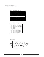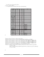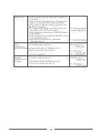
connecter‑pin
Signal
Input or Output
1
POWER̲CONT
OUT
2
DISPLAY̲POWER
OUT
3
OPTION̲A
OUT
4
OPTION̲B
OUT
5
OPTION̲C
OUT
6
OPTION̲D
OUT
7
OPTION̲E
OUT
8
OPTION̲F
OUT
9
IN1(Composite1)
OUT
10
IN2(Composite2)
OUT
11
IN3(Composite3)
OUT
12
IN4(Component)
OUT
13
IN5(RGB1)
OUT
14
IN6(RGB2)
OUT
15
IN7(RGB3)
OUT
16
IN8(RGB4)
OUT
17
CAT5
OUT
18
SUB
OUT
19
OFF(MUTE)
OUT
20
‑
21
GND
22
GND
23
GND
24
GND
25
GND
26
27
28
29
30
31
POWER̲CONT
IN
32
DISPLAY̲POWER
IN
33
IN
34
IN
35
IN
36
IN
37
IN
38
IN
OPTION̲A
OPTION̲B
OPTION̲C
OPTION̲E
OPTION̲F
OPTION̲D
IN1(Composite1)
IN2(Composite2)
IN3(Composite3)
IN4(Component)
IN5(RGB1)
IN6(RGB2)
IN7(RGB3)
IN8(RGB4)
CAT5
IN
IN
IN
IN
IN
IN
IN
IN
39
40
41
42
43
44
45
46
47
48
49
50
SUB
OFF(MUTE)
−
IN
IN
IN
+5V
+5V
+5V
+5V
+5V
6. Parallel interface
This product can be controlled by connecting parallel interface.
This product can be controlled as the same operation by front buttons.
Parallel connector signal arrangement
‑22‑

