ATTACHING LOADER
IMPORTANT:
Never attempt loader attachment on grades which are not reasonably level.
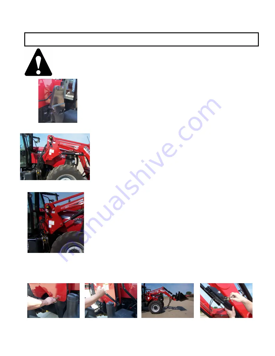
1. Check to be sure that the surfaces of the mounts are free of
obstructions. (Fig 8-1)
2. Drive the tractor slowly and carefully in between the loader arms
only far enough to permit hook-up of the hydraulic system hoses.
3. Once all hoses have been properly coupled drive the tractor forward
checking to insure that the top pivot shaft on each loader upright
clears the top cradle on each mount tower. (Fig. 8-2)
4. Allow the top pivot shaft to settle into the cradle on the top of each
mount tower. After the uprights slide into the mount raise the loader
slowly to engage firmly into the mount cradles. (Fig. 8-3)
5. To lock the loader onto the mount, install the two 669514 – 1 3/8”
diameter mount pins into the outside of the upright through the mount
tightener, and pin with hitch pin on other side. (Fig. 8-4)
6. To secure the loader to the mount tighten the 1” bolt at the back of
the mount tower. (Fig. 8-5) Re-check bolts after first three hours of
use.
7. After both uprights are secured to the mounts, raise the loader still
further to disengage and store the loader stands with provided mount
pins. (Fig 8-6) & (Fig 8-7)
8. Prior to operation, be certain to review all safety and operation
information contained within this manual. Check bolts on back of
mount or the first 3 hours of use, then check periodically during
normal maintenance procedure.
Page 8
Fig 8-1
Fig 8-7
Fig 8-4
Fig 8-6
Fig 8-5
Fig 8-3
Fig 8-2
Summary of Contents for Pro 2585
Page 8: ...SAFETY DECALS Page 6...
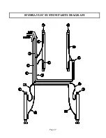
Page 19: ...HYDRAULIC SYSTEM PARTS DIAGRAM Page 17...
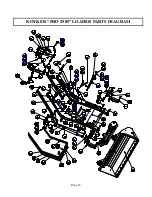
Page 20: ...KOYKER PRO 2585 LOADER PARTS DIAGRAM Page 18...
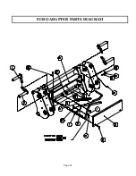
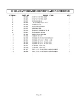
Page 23: ...EURO ADAPTER PARTS DIAGRAM Page 21...
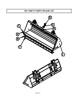
Page 25: ...BUCKET PARTS DIAGRAM Page 23...
Page 27: ...ACCUMULATOR KIT PARTS DIAGRAM Page 25...


