TORQUE SPECIFICATIONS
Page 36
1. Tightening Bolts & Nuts
Check all loader bolts and nuts for tightness every 50 working hours. The movement of the loader
over rough terrain may cause bolts to come under pressure and over a long period of time some
slight stretching of the bolt may occur. The slack created may need to be taken up by tightening.
Please refer below for recommended torque settings.
Metric Recommended Torque Settings
Class 8.8 Class 10.9
Lubricated Dry Lubricated Dry
Size N*m Lb-ft N*m Lb-ft N*m Lb-ft N*m Lb-ft
M6 ...................... 9 6.5 11 8.5 ...................... 13 9.5 17 12
M8 ...................... 22 16 28 20 ....................... 32 24 40 30
M10 .................... 43 32 55 40 ....................... 63 47 80 60
M12 .................... 75 55 95 70 ....................... 110 80 140 105
M14 .................... 120 88 150 110 ..................... 175 130 225 165
M16 .................... 190 140 240 175 ..................... 275 200 350 225
M18 .................... 260 195 330 250 ..................... 375 275 475 350
M20 .................... 375 275 475 350 ..................... 530 400 675 500
M22 .................... 510 375 650 475 ..................... 725 540 925 675
M24 .................... 650 475 825 600 ..................... 925 675 1150 850
M27 .................... 950 700 1200 875 ..................... 1350 1000 1700 1250
M30 .................... 1300 950 1650 1200 ................... 1850 1350 2300 1700
M33 .................... 1750 1300 2200 1650 ................... 2500 1850 3150 2350
M36 .................... 2250 1650 2850 2100 ................... 3200 2350 4050 3000
SAE Recommended Torque Settings
Grade 5 Grade 8
Lubricated Dry Lubricated Dry
Size N*m Lb-ft N*m Lb-ft N*m Lb-ft N*m Lb-ft
1/4 ....................... 9.5 7 12 9 ......................... 13.5 10 17 12.5
5/16 ..................... 20 15 25 18 ....................... 28 21 35 26
3/8 ....................... 35 26 44 33 ....................... 50 36 63 46
7/16 ..................... 55 41 70 52 ....................... 80 58 100 75
1/2 ....................... 85 63 110 80 ....................... 120 90 150 115
9/16 ..................... 125 90 155 115 ..................... 175 130 225 160
5/8 ....................... 170 125 215 160 ..................... 215 160 300 225
3/4 ....................... 300 225 375 280 ..................... 425 310 550 400
7/8 ....................... 490 360 625 450 ..................... 700 500 875 650
1 .......................... 725 540 925 675 ..................... 1050 750 1300 975
1-1/8 ................... 900 675 1150 1200 ................... 2050 1500 2600 1950
1-3/8 ................... 1700 1250 2150 1550 ................... 2700 2000 3400 2550
1-1/2 ................... 2250 1650 2850 2100 ................... 3600 2650 4550 3350
DO NOT use these values if a different torque value or tightening procedure is given for a
specific application. Torque values listed are for general use only and include a +/- 10%
variance. Check tightness of fasteners periodically. DO NOT use air powered wrenches.
Shear bolts are designed to fail under predetermined loads. Always replace shear bolts with
identical grade.
Summary of Contents for Pro 2585
Page 8: ...SAFETY DECALS Page 6...
Page 19: ...HYDRAULIC SYSTEM PARTS DIAGRAM Page 17...
Page 20: ...KOYKER PRO 2585 LOADER PARTS DIAGRAM Page 18...
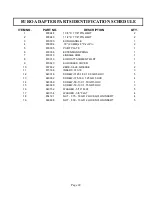
Page 23: ...EURO ADAPTER PARTS DIAGRAM Page 21...
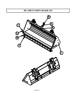
Page 25: ...BUCKET PARTS DIAGRAM Page 23...
Page 27: ...ACCUMULATOR KIT PARTS DIAGRAM Page 25...

