3-58
3-6
Built-in analog data input/output function
The SJ Ether series can use analog-type CPU modules or analog-type extended I/O modules to enable analog-data input and output.
Refer to 3-1 CPU Module and 3-3 Extended I/O Module for the specifications of each module.
3-6-1
Operation of the built-in module
(1)
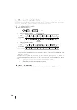
Input: Channel Scan Sequence
Analogue input data is digitized in an A/D converter and written to a specified register. The output outputs the value stored
in the register for each scan.
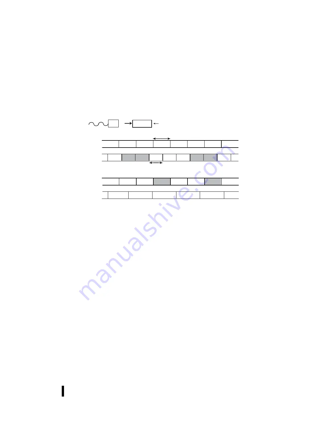
The diagram above describes the CH1 of the analog type CPU module. Since register updates and scan times are not
synchronized, the data loaded per scan is as shown in 1. and 2. from the relationship between register update time and scan
time.
①
The register update time > scan time can read the same data before R7601 is updated.
②
The register update time < scan time contains data that is not read.
(2)
Output: Channel Update Sequence
The program results are written to the register for output and analog signals are output by the D/A converter.
R7601
A/D
CH1
…
A3
A4
A5
A6
A7
A6
A5
A4
A3
A4
A5
A6
A7
A6
A5
A4
A3
A4
A4
A5
A6
A7
A6
A6
A5
A3
A4
A5
A7
A6
A4
R7601
スキャンのタイミング
読込まれたデータ
R7601
スキャンのタイミング
読込まれたデータ
①レジスタ更新時間>スキャンタイム
②レジスタ更新時間<スキャンタイム
レジスタ更新時間
スキャンタイム
スキャン
↓
↓
↓
↓
↓
↓
↓
↓
↓
↓
↓
↓
↓
↓
↓
↓
Scan
Register renewal time > Scan time
Register renewal time
Scan time
Register renewal time < Scan time
Timing of scan
Data which was read
Timing of scan
Data which was read
Summary of Contents for Kostac SJ-Ether Series
Page 1: ...English version of the KOSTAC SJ Ether series user s manual SJ ETHER USER M...
Page 12: ......
Page 13: ...1...
Page 14: ......
Page 88: ......
Page 89: ......
Page 113: ...3 24 Note Refer to 6 3 3 Module Assembly for connections and locks between modules...
Page 153: ......
Page 156: ...flashing OFF Not sent H W RX Green flashing Receiving H W OFF Not received H W...
Page 161: ...4 8...
Page 221: ......
Page 310: ...Chapter 7 Maintenance...
Page 311: ......

