3-62
3-6-5
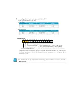
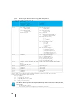
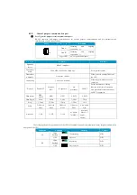
Detailed register information for setting optional analog module
The first register number of each Slot shall be Rn.
Register number
Model number
C0-04AD-1
、
C0-04AD-2
、
C0-4AD2DA-1
、
C0-4AD2DA-2
、
C0-04DA-1
、
C0-04DA-2
C0-04THM
C0-04RTD
Rn + 0
Bit15: BIN/BCD selection
0=BCD, 1=BIN
Bit14 : Input Error Setting
0=Hold, 1=Clear
Bit13-0: Not use (0)
Bit15: BIN/BCD selection
0=BCD, 1=BIN
Bit14 : Input Error Setting
0=Hold, 1=Clear
Bit13-8: Not use (0)
Bit07 : Disconnection detection setting (*1)
0=Disable, 1=Enable <default>
Bit06: Temperature-unit setting
0 = F
1 = C <default>
Bit05 04: Filter Frequency (Fixed)
00=3.75 Hz
01=7.5 Hz
10 = 15 Hz <Fix>
11=30 Hz
Bit03 00: Ch number setting (0-3)
0(0000)=Enable Channel 1
1(0001)=Enable Channel 1+2
2(0010)=Enable Channel 1+2+3
3(0011)=Enable Channel 1+2+3+4
Rn + 1
Preliminary
Set sensor type (temperature range)
Bit15 12: Ch4 Range setting (0-F)
Bit11 8: Ch3 Range setting (0 to F)
Bit 7 4: Ch2 Range setting (0 to F)
Bit 3-0: Ch1 Range setting (0 to F)
Rn + 2
Setting of conversion data storage top register
number
(binary value: R2000
⇒
400)
Setting of conversion data storage top register number
Rn + 3
Preliminary
Ch1 error flag (*2)
Rn + 4
Preliminary
Ch2 error flag
Rn + 5
Preliminary
Ch3 error flag
Rn + 6
Preliminary
Ch4 error flag
Rn + 7
Preliminary
Preliminary
※
When 1:C0-04RTD is used, Burn-out setting is enabled unconditionally (1) and only C0-04THM can be set variable.
※
2: Conversion error flag definition and all Ch are common.
Bit 15 to 3: undefined
Bit 2: OVER RANGE (over limit)
Bit 1: UNDER RANGE (over lower limit)
Bit 0: BURN OUT (disconnection)
Note: When the bit14 of register Rn+0 for setting the optional analogue module is turned on, this is the last time when
an error occurs.
The analogue value is retained.
When the bit14 is turned off, the analogue value is 0000 when an error occurs.
Summary of Contents for Kostac SJ-Ether Series
Page 1: ...English version of the KOSTAC SJ Ether series user s manual SJ ETHER USER M...
Page 12: ......
Page 13: ...1...
Page 14: ......
Page 88: ......
Page 89: ......
Page 113: ...3 24 Note Refer to 6 3 3 Module Assembly for connections and locks between modules...
Page 153: ......
Page 156: ...flashing OFF Not sent H W RX Green flashing Receiving H W OFF Not received H W...
Page 161: ...4 8...
Page 221: ......
Page 310: ...Chapter 7 Maintenance...
Page 311: ......

