4-2
4-1
Communications port
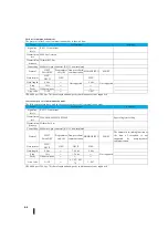
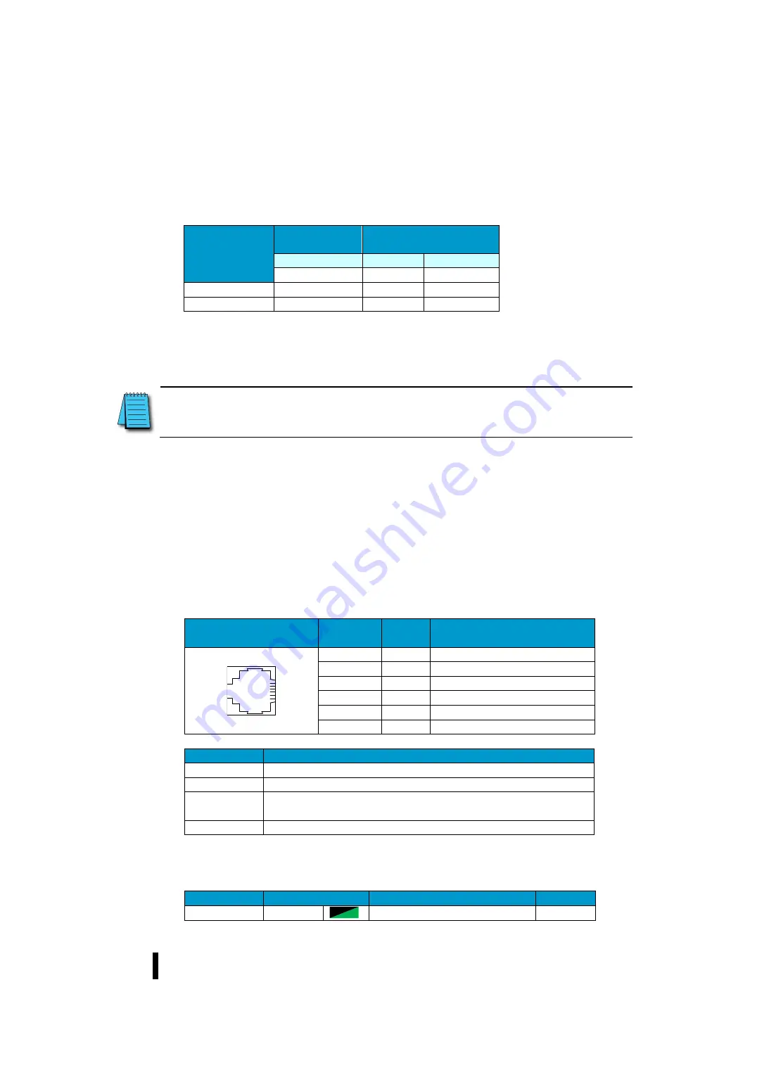
The presence or absence of SJ-Ether communication ports is as follows.
CPU
Module
Programmer port
General purpose
communication port
Port 1
Port 2
Port 3
RS-232C
RS-485
Ethernet
Basic
○
○
○
Analog
○
○
○
For network specifications, RS-232C is suitable for simple networks such as communication between two devices with a short
distance (max. 15 m). On the other hand, RS-485 is suitable for networks connecting long distances (max. 1000 m) and multi-drop
networks (up to 2-32 devices).
4-1-1
Programmer port
The programmer communication port can select the fixed serial communication mode and the general purpose serial
communication mode.
When the forced RUN mode is detected with the mode switching switch in the RUN state, the general-purpose serial
communication mode is set.
When the general-purpose serial communication mode is selected, the general-purpose serial communication mode is
maintained even after changing the mode switching switch. To return from the general-purpose serial communication
mode to the fixed serial communication mode, switch the mode switching switch from RUN to TERM three times
within five seconds.
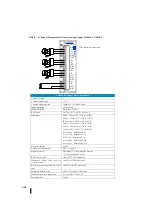
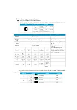
The pin assignment and specifications for port 1 are as follows.
Port 1
Pin number
Signal
name
Description
1
0 V
+5 V, signaling 0 V
2
+5 V
Power supply for programmer supply
3
RXD
Received data (RS 232 C)
4
TXD
Transmitted data (RS 232 C)
5
+5 V
Power supply for programmer supply
6
0 V
+5 V, signaling 0 V
I t e m
Performance
Signaling levels
RS-232C compliant
Transmission rate
9600 bps (fixed)
Transmission
distance
Within the 10 m
Connecting
Modular 6-pin connector (RJ-12), non-insulated
※
300/600 per 1200 bps, 7-bit data length and no Parity combinations are not supported
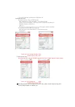
The following shows the specifications of the LED for communication port communication status display mounted on the front
panel of the CPU.
Indication
Condition
Meaning
Control
TX
Green
Transmitting
H/W
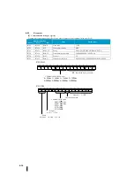
Note: Terminal resistance is required at both ends of the RS-485 network. The resistance must be selected
according to the cable impedance rating (100 to 500 ohms).
Refer to 1-4-1 "Top link" for connection example.
Summary of Contents for Kostac SJ-Ether Series
Page 1: ...English version of the KOSTAC SJ Ether series user s manual SJ ETHER USER M...
Page 12: ......
Page 13: ...1...
Page 14: ......
Page 88: ......
Page 89: ......
Page 113: ...3 24 Note Refer to 6 3 3 Module Assembly for connections and locks between modules...
Page 153: ......
Page 156: ...flashing OFF Not sent H W RX Green flashing Receiving H W OFF Not received H W...
Page 161: ...4 8...
Page 221: ......
Page 310: ...Chapter 7 Maintenance...
Page 311: ......


