4-22
(7)
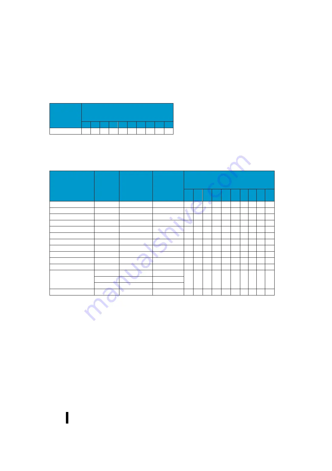
Client mode address mapping table (MRX/MWX counterpart device: generic MODBUS/TCP compatible
products)
MODBUS scope
(decimal
number)
Corresponding function code
(○:Corresponding,
△
: Partially supported,-: Not
supported)
01
02
03
04
05
06
07
08
15
16
1
~
465536
○
○
○
○
○
○
○
-
○
○
When the communication partner (slave device) is SJ-Ether in function code 07, one byte data of Q0-Q7 can be read.
If the other party is not SJ-Ether, it complies with the specifications of the slave device.
(8)
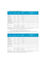
Client mode address mapping table (RX/WX)
Memory type
Score
(decimal
number)
PLC range
(octal number)
MODBUS scope
(decimal
number)
Corresponding function code
(○:Corresponding,
△
: Partially supported,-: Not
supported)
01
02
03
※
04
※
05
06
07
08
15
16
Input (I)
1024
I0
~
1777
2048
~
3071
-
○
-
-
-
-
-
-
-
-
Special relay (SP)
512
SP0
~
777
3072
~
3583
-
○
-
-
-
-
-
-
-
-
Output (Q)
1024
Q0
~
1777
2048
~
3071
○
-
-
-
-
-
-
-
○
-
Internal relay (M)
2048
M0
~
3777
3072
~
5119
○
-
-
-
-
-
-
-
○
-
Timer contact (T)
256
T0
~
377
6144
~
6399
○
-
-
-
-
-
-
-
○
-
Counter contact (C)
256
C0
~
377
6400
~
6655
○
-
-
-
-
-
-
-
○
-
Stage state bit (S)
1024
S0
~
1777
5120
~
6143
○
-
-
-
-
-
-
-
○
-
Global input (GI)
2048
GI0
~
3777
0
~
2047
-
○
-
-
-
-
-
-
-
-
Global Output (GQ)
2048
GQ0
~
3777
0
~
2047
○
-
-
-
-
-
-
-
○
-
Timer elapsed value (R)
256
R0
~
377
0
~
255
-
-
○
○
-
-
-
-
-
○
Counter elapsed value (R)
256
R1000
~
1377
512
~
767
-
-
○
○
-
-
-
-
-
○
Data register (R)
256
R400
~
777
256
~
511
-
-
○
○
-
-
-
-
-
○
3072
R1400
~
7377
768
~
3839
8192
R10000
~
27777
4096
~
12287
Special register (R)
256
R7400
~
7777
3840
~
4095
-
-
○
○
-
-
-
-
-
○
※
When using the RX command, the function code is switched from 03 to 04 by adding the number "4" to the digit at the top of the data size
setting.
Summary of Contents for Kostac SJ-Ether Series
Page 1: ...English version of the KOSTAC SJ Ether series user s manual SJ ETHER USER M...
Page 12: ......
Page 13: ...1...
Page 14: ......
Page 88: ......
Page 89: ......
Page 113: ...3 24 Note Refer to 6 3 3 Module Assembly for connections and locks between modules...
Page 153: ......
Page 156: ...flashing OFF Not sent H W RX Green flashing Receiving H W OFF Not received H W...
Page 161: ...4 8...
Page 221: ......
Page 310: ...Chapter 7 Maintenance...
Page 311: ......


