4-26
(5)
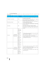
Status notification relay
When the general purpose communication port (Port2) is set to M-NET, the internal relay M740 to M767 is occupied as the state
notification relay.
Name
Internal relay
number
Configuration complete flag
M740
Be sure to use the SET command to turn ON when setting is
completed by the user program.
After confirming that this internal relay is on, a series of
operations, such as setting checking, are started.
Received data clear flag
M741
This relay specifies whether received data is cleared (data 0 is
written) or not when an error occurs.
The received data is cleared when OFF.
Restart flag
M743
This is a command flag for restarting M-NET communication
when an error occurs.
This is valid only when the master station is operated.
When the PLC operation mode is changed from STOP to RUN
when the master station is operated, the PLC operation mode is
restarted.
Error flag
At the master
station and at the
satellite station
Parent
station :M750
Slave-station
1:M751
Slave-station
2:M752
Slave-station
3:M753
Slave-station
4:M754
Slave-station
5:M755
Slave-station
6:M756
Slave-station
7:M757
ON when setting error is detected during own setting check and
connection preparation sequence.
Turns ON when no communication is detected during the
connection preparation sequence or normal sequence.
Connection preparation sequence turns ON when parity error is
detected during normal sequence.
Connection ready flag
At the master
station and at the
satellite station
Slave-station
1:M761
Slave-station
2:M762
Slave-station
3:M763
Slave-station
4:M764
Slave-station
5:M765
Slave-station
6:M766
Slave-station
7:M767
This switch is turned ON when the connection preparation
sequence is normal and completes normally.
In the case of a satellite station, only the bits of the Slave-station
number of the own station are turned on.
At the master station, all the satellite station numbers in the
network are turned on.
Summary of Contents for Kostac SJ-Ether Series
Page 1: ...English version of the KOSTAC SJ Ether series user s manual SJ ETHER USER M...
Page 12: ......
Page 13: ...1...
Page 14: ......
Page 88: ......
Page 89: ......
Page 113: ...3 24 Note Refer to 6 3 3 Module Assembly for connections and locks between modules...
Page 153: ......
Page 156: ...flashing OFF Not sent H W RX Green flashing Receiving H W OFF Not received H W...
Page 161: ...4 8...
Page 221: ......
Page 310: ...Chapter 7 Maintenance...
Page 311: ......


