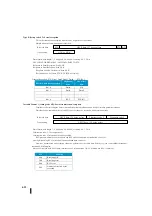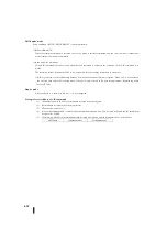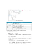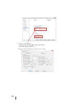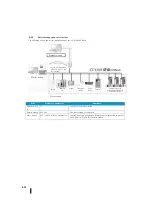
C)Variable format 2: Type 70
1)Transmission
Data can be transmitted according to the data format set by the setting register R7651.
Mode 70 does not have flow control (X-ON/X-OFF and RTS/CTS control).
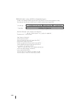
2)About Reception
・
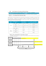
R751, R7651: Sets the reception end time.
Measurement of the reception completion setting time starts after the lapse of the communication time of three charact
ers transmission time.
(
※
Data length 7 bits + no parity bit: unsupported
・
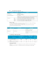
Variable format 2: Configuration of received data storage for type 70
Received data storage register: register number set at the top register R754, R7654 of the non-procedure setting.
The lower layer of received data storage register +0 is reception status.
Received data storage register +1 is the number of received data bytes. Is substituted with a binary value.
Up to 128 (80h).
Received data is stored in the lower layer of the received data storage register +2.
You receive up to 128 bytes of data continuously.
Received data after byte 129 is ignored until the reception completion is recognized.
When the reception completion is recognized, the "F0" indicating that the number of received data exceeds is assign
ed to the communication status.
Data from bytes 1 to 128 is stored in the received data storage register.
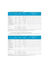
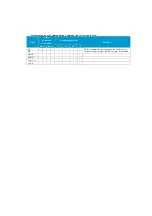
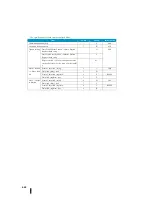
Register number
Reception completion ti
me
Data Format
※
Settings
Contents
Settings
Contents
Port 1
Port 2
Data length
Stop bit
Parity bits
R751
R7651
00xx
0 ms
Xx02
7
1
Even-numbered
01xx
2 ms
Xx03
7
1
Odd-numbered
02xx
5 ms
Xx0A
7
2
Even-numbered
03xx
10 ms
Xx0B
7
2
Odd-numbered
04xx
20 ms
Xx04
8
1
Without
05xx
50 ms
Xx05
8
2
Without
06xx
100 ms
Xx06
8
1
Even-numbered
07xx
500 ms
Xx07
8
1
Odd-numbered
Xx0E
8
2
Even-numbered
Xx0F
8
2
Odd-numbered
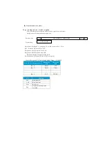
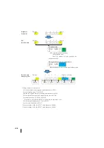
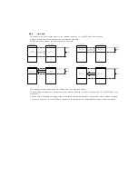
Transmitting data
1
Generally, when the same amount of non-communication
time as three characters is detected,
the reception is judged to be complete.
2 3 4 5 6
7 8 9
10 11 12
When the reception completion time is set, it is judged to be complete
when the same amount of time, as three characters plus set time takes, is passed.
1 2 3
Transmitting data
6 characters are reflected in the received data.
1 2 3 4 5 6
1 2 3 4 5 6 7 8 9
Transmitting data
1 2 3 4 5 6
7 8 9
10 11 12
1 2 3
Transmitting data
Setting
time
1 2 3
Setting
time
9 characters are reflected in the received data.
Summary of Contents for Kostac SJ-Ether Series
Page 1: ...English version of the KOSTAC SJ Ether series user s manual SJ ETHER USER M...
Page 12: ......
Page 13: ...1...
Page 14: ......
Page 88: ......
Page 89: ......
Page 113: ...3 24 Note Refer to 6 3 3 Module Assembly for connections and locks between modules...
Page 153: ......
Page 156: ...flashing OFF Not sent H W RX Green flashing Receiving H W OFF Not received H W...
Page 161: ...4 8...
Page 221: ......
Page 310: ...Chapter 7 Maintenance...
Page 311: ......

