(5)
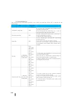
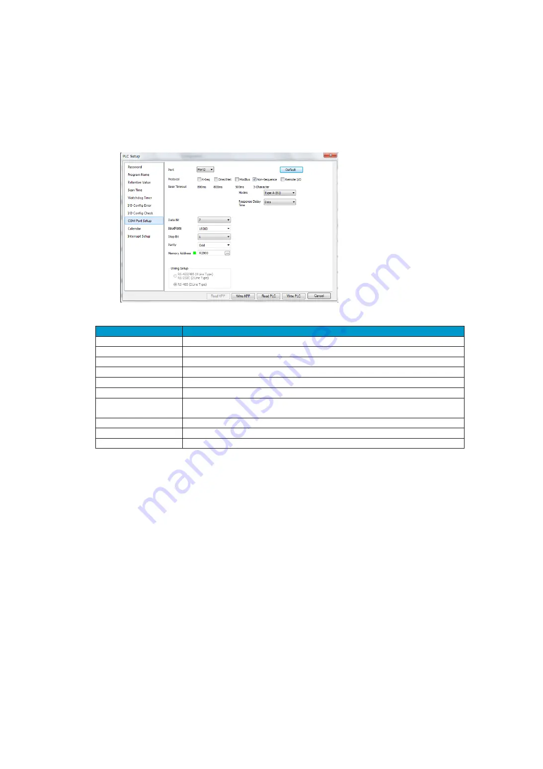
Communication setting using KPP tools (Port2)
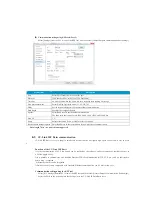
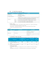
Select [Settings] from the PLC menu of the KPP tool, and then select [General Purpose Communication Port Settings].
Setting item
Description
Port
Select Port 2 from the list box for the port.
Protocol
Click the check box to the left of [No Procedure].
Time-out
An error occurs when the port waits for a response after sending a message.
Non-procedural mode
Select No-Step Operation mode (61, 62, 6B, 70).
Delay
Set the response delay time for non-procedure communication.
Data length
Specifies the length of the data.
Speeds
Select Baud rate for unscheduled communication.
The baud rates that can be set are 2400, 4800, 9600, 19200, and 38400 bps.
Stop bit
1,2
Parity
Select either None, Even, or Odd for error check parity.
Received data storage register Enter the address of the received data for non-procedure communication.
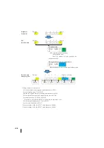
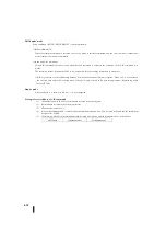
Data length 7 bits + no parity bit: unsupported
4-3
CC-Link IEF Basic communication
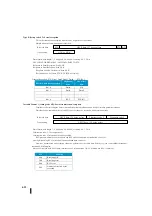
CC-Link IEF Basic is easy to adapt to small-scale devices that do not require high-speed control and is easy to acces
s.
Function of the CC-Link IEF Basic
1)Cyclic communication of CC-Link Family can be realized by the software, and great amount of available devices ca
n be line-upped easily.
2)It is possible to communicate with standard Ethernet TCP/IP communication (HTTP, FTP, etc.), and no dedicated co
ntrol wiring is required.
Ethernet networks can be integrated.
3)Field network systems compatible with standard Ethernet communication can be built at low cost.
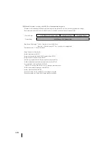
Communication setting using the KPP tool
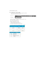
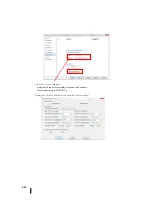
Select [PLC Settings] from the PLC view of the KPP tool, and then select [General Purpose Communication Port Settings].
Select the Port3 on the port and place the check point in the CC-Link IE Field Basic slave.
Summary of Contents for Kostac SJ-Ether Series
Page 1: ...English version of the KOSTAC SJ Ether series user s manual SJ ETHER USER M...
Page 12: ......
Page 13: ...1...
Page 14: ......
Page 88: ......
Page 89: ......
Page 113: ...3 24 Note Refer to 6 3 3 Module Assembly for connections and locks between modules...
Page 153: ......
Page 156: ...flashing OFF Not sent H W RX Green flashing Receiving H W OFF Not received H W...
Page 161: ...4 8...
Page 221: ......
Page 310: ...Chapter 7 Maintenance...
Page 311: ......


