5-4
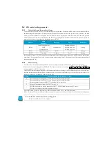
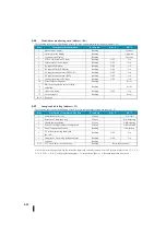
Features of PID control
Specification
Number of loops
Selectable, up to 16 types
Required CPU register capacity
32 words per loop (register) or 64 words for lamp/soak
PID algorithm
Position or velocity form
Operating direction
Heating or cooling operation
Deviation curve
Select from the square of linear and deviation.
Sampling-period
(Time
interval
for
PID
calculation)
0.05 to 99.99 seconds (programmable by the user)
Minimum sampling period
0.05 seconds (1-16 loops)
Controlling mode
Automatic, manual, and cascade
Sink/soak generator
Up to 8 lamps/soak step per loop (16 categories)
PV curve
Standard linear or square root extraction (for flow meter input)
Set point (target value)
Minimum/Maximum set point value is specified.
Output value (measured value)
Minimum/Maximum output value is specified.
Gain (proportional)
Specify gain 0.01 to 99.99.
RESET (INTEGRATION) TIME
Reset time 0.1 to 999.8 (in seconds or minutes)
Rate (derivative) time
Specify the differential time from 0.01 to 99.99 seconds.
Differential filter constant
Specify the differential filter constants 1 to 20.
Bumper transfer I
When switching manual control to automatic control,
Bias and set points are automatically initialized.
Bumper transfer II
When switching manual control to automatic control, the bias equal to control output is
automatically set.
Step bias
The bias can be adjusted in proportion to the large variation of the set point.
Reset windup
When the control output reaches 0% or 100%, the integrator is disabled (to prevent
significant overshooting due to integral operation).
Zone of insensitivity of deviation
Specify the tolerance (plus/minus) for the deviation (SP-PV). This area does not cause
an error, and the control output value is calculated.
When the deviation is within this range, the deviation is controlled as zero
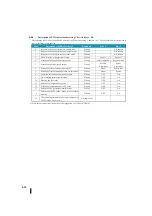
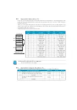
Alarming function
Specification
Dead-band
Alarm insensitivity zone (0.1%-5%) for all alarms is specified.
PV alarm
Set PV alarm settings for low-low, low, High, and High-high conditions.
PV deviation
Deviation alarm shown as the difference between the PV value (measured value) and the
SP value (target value)
Rate of the change
PV detects a user-specified value violation
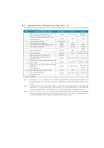
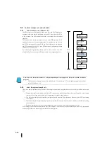
Note: When analogue input/output of the SJ Ether unit is used, go to special register R7640 (analogue input/output
setting register)
Set the data format to "BIN".
On the PID setting/PID monitor of KPP, use the "BCD" format.
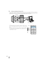
アナログ入出力データのデータ形式をBIN形式設定とする値を設定。
※入出力タイプ指定は、使用機器に応じた設定としてください。
ここでは、電圧に設定しています。
アナログ入出力データフォーマット、入出力タイプ格納特殊レジス
タへ設定値を書き込む
SP0
LDS
KE000
OUTW
R7600
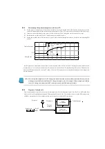
Set the value whose the data format of analog I/O data is BIN format setting.
*The setting of I/O type specification should be suitable for the device you use.
It is set to voltage here.
Write the set value to the data format of analog I/O and I/O type storage special
register.
Summary of Contents for Kostac SJ-Ether Series
Page 1: ...English version of the KOSTAC SJ Ether series user s manual SJ ETHER USER M...
Page 12: ......
Page 13: ...1...
Page 14: ......
Page 88: ......
Page 89: ......
Page 113: ...3 24 Note Refer to 6 3 3 Module Assembly for connections and locks between modules...
Page 153: ......
Page 156: ...flashing OFF Not sent H W RX Green flashing Receiving H W OFF Not received H W...
Page 161: ...4 8...
Page 221: ......
Page 310: ...Chapter 7 Maintenance...
Page 311: ......

