5-8
5-2-3
Set the size and position of the control table.
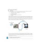
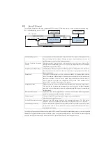
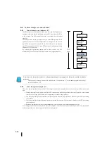
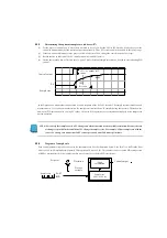
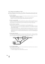
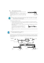
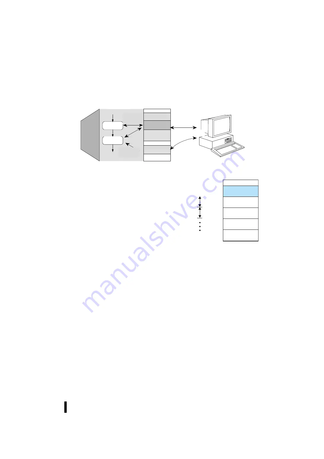
As shown below, when the STOP changes to RUN mode, the CPU reads control parameters. The CPU then captures the
position and number of loops in the control table. During ladder program execution, PID control uses control data to execute
operations, alarms, etc. Some control table parameters are read/written for each control operation.
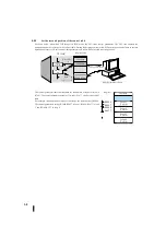
The control parameter table contains data for the number of loops selected in
R7641. The control parameter occupies 32 words (0 to 37 octal) as the control
table.
For example, in an application that uses four loops, the start address is R2000.
The control parameters occupy R2000-R2037 in loop 1, R2040-R2077 in loop
2, and R2140-R2177 in loop 4.
R 2000
R 2037
R 2040
R 2077
レジスタ
ユーザデータ
ループ
#1
32
ワード
ループ
#2
32
ワード
ループ
#3
32
ワード
ループ
#4
32
ワード
CPU
タスク
レジスタ空間
設定/監視
KPP
プログラミングソフトウェア
ユーザデータ
ループデータ
セットアップパラメータ
R7640,R7641
読み出し/
書き込み
読み出し
(電源投入時)
ラダー
プログラム
PID
ループ
タスク
CPU task
Register area
User data
Loop data
Setup parameter
Setting/observation
KPP programming software
Read/Wri
te
Read
Ladder
Program
PID loop
task
Register
User data
Loop #1
32 words
Loop #2
32 words
Loop #3
32 words
Loop #4
32 words
Summary of Contents for Kostac SJ-Ether Series
Page 1: ...English version of the KOSTAC SJ Ether series user s manual SJ ETHER USER M...
Page 12: ......
Page 13: ...1...
Page 14: ......
Page 88: ......
Page 89: ......
Page 113: ...3 24 Note Refer to 6 3 3 Module Assembly for connections and locks between modules...
Page 153: ......
Page 156: ...flashing OFF Not sent H W RX Green flashing Receiving H W OFF Not received H W...
Page 161: ...4 8...
Page 221: ......
Page 310: ...Chapter 7 Maintenance...
Page 311: ......


