5-10
5-2-4
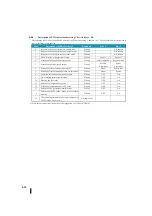
Description of PID control mode setting 1 bit (A 00)
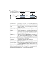
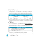
The following table shows the definition of each bit of PID mode setting 1 (a 00). The use of this word is discussed in
more detail later in this chapter.
Bites
Description of PID mode setting 1
Read/write
Bit = 0
Bit = 1
0
Request to change operation to manual mode
Writing
–
0
⇒
1 request
1
Request to change operation to automatic mode
Writing
–
0
⇒
1 request
2
Request to change operation to cascade mode
Writing
–
0
⇒
1 request
3
Mode selection of bumper processing
Writing
Mode I
Mode II
4
Selection of heating and cooling control
Writing
Direct operation
Reverse action
5
Selection of position/speed output
Writing
Position
Algorithm
Speeds
Algorithm
6
Selection of linear/root operations for PV
Writing
Linear
Square root
7
Selection of linear/square operation for deviation
Writing
Linear
Square
8
Deviation insensitive band control enable
Writing
OFF
On
9
Time filtering for differential terms
Writing
OFF
On
10
Freezing the bias value
Writing
OFF
On
11
Selection of lamp/soak operation
Writing
OFF
On
12
Selection of alarm monitor for PV value
Writing
OFF
On
13
Selection of PV deviation alarm monitor
Writing
OFF
On
14
Selection of the PV value change rate over alarm
monitor
Writing
OFF
On
15
The control operation mode becomes independent
of CPU mode when set to 1
Not applicable
-
-
※
Since the automatic transfer function is not supported, set 15 bits to "OFF(0)".
Summary of Contents for Kostac SJ-Ether Series
Page 1: ...English version of the KOSTAC SJ Ether series user s manual SJ ETHER USER M...
Page 12: ......
Page 13: ...1...
Page 14: ......
Page 88: ......
Page 89: ......
Page 113: ...3 24 Note Refer to 6 3 3 Module Assembly for connections and locks between modules...
Page 153: ......
Page 156: ...flashing OFF Not sent H W RX Green flashing Receiving H W OFF Not received H W...
Page 161: ...4 8...
Page 221: ......
Page 310: ...Chapter 7 Maintenance...
Page 311: ......

