5-2-5
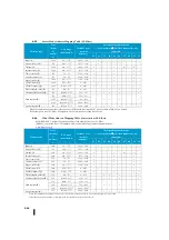
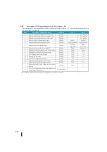
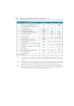
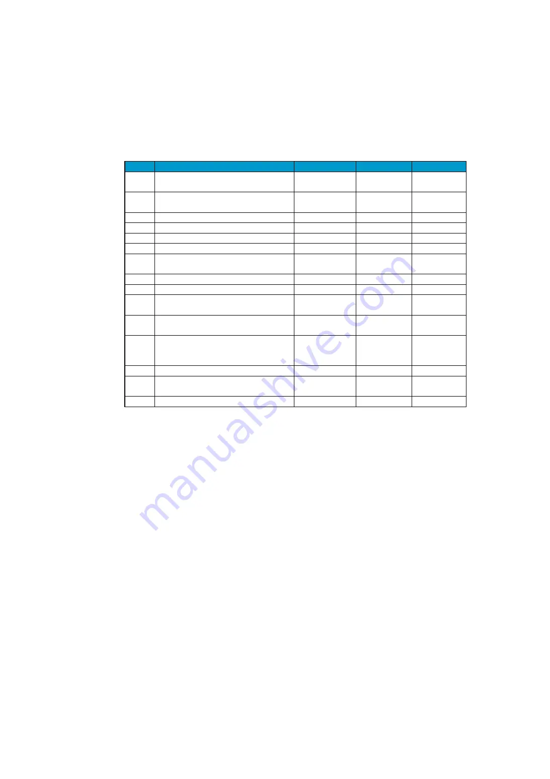
Explanation of 2 bits of PID control mode setting (A 01)
The following table shows the definition of each bit of PID mode setting 2 (a 01). The use of this word is discussed in
more detail later in this chapter.
Bites
Description of PID mode setting 2
Read/write
Bit = 0
Bit = 1
0
Input (PV) and positive/negative selection of
control output range (see Notes 1 and 2)
Writing
Positive only
Positive and
negative
1
Selection of input/output data (analog) format
(see Notes 1 and 2)
Writing
12 bits
15 bits
2
Analog input filter function
Not applicable
-
-
3
SP input limit setting is enabled.
Writing
OFF
On
4
Unit selection of reset time (integration time)
Writing
Second
Minute
5
Auto-tuning PID algorithm
Writing
Close-loop
Open-loop
6
Auto tuning selection
Writing
PID
PI only
(rate = 0)
7
Start of auto tuning
Read/write
Executed
Starting execution
8
PID calculation clock (used internally)
Reading
-
-
9
16-bit input/output data format selection
(see Notes 1 and 2)
Writing
Other than 16 bits
16-bit selection
10
Selective Data Formats for Input and Output (see
Notes 2 and 3)
Writing
Same format
Different format
11
Positive/Positive and Negative selection of control
output range
(see Notes 2 and 3)
Writing
Positive only
Positive and
negative
12
Data Format Selection (see Notes 2 and 3)
Writing
12 bits
15 bits
13
16-bit data format selection
(see Notes 2 and 3)
Writing
Other than 16 bits
16-bit selection
14-15
Scheduled
-
-
-
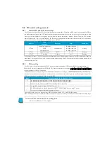
Note 1:
If the value of bit 9 is 0, the value is read in the format set with bits 0 and 1 (positive/positive and negative, 12/15
bits). If the value of bit 9 is 1, the setting of bits 0 and 1 is disabled, and bit 9 defines the data format (positive range,
16 bits).
Note 2:
If the value of bit 10 is 0, then the values of bits 0, 1, and 9 define the input and output ranges and data formats
(values of bits 11, 12, and 13 are not read). If the value of bit 10 is 1, then the values of bits 0, 1, and 9 define only
the input range and data range, and the values of bits 11, 12, and 13 define the output range and data format.
Note 3:
If bit 10 has a value of 1 and bit 13 has a value of 0, then the values of bits 11 and 12 define the output range and data
format (positive/positive and negative, 12/15 bits). If each of bits 10 and 13 has a value of 1, then the settings of bits
11 and 12 are disabled and bit 13 defines the data format. (Positive range, 16 bits).
Summary of Contents for Kostac SJ-Ether Series
Page 1: ...English version of the KOSTAC SJ Ether series user s manual SJ ETHER USER M...
Page 12: ......
Page 13: ...1...
Page 14: ......
Page 88: ......
Page 89: ......
Page 113: ...3 24 Note Refer to 6 3 3 Module Assembly for connections and locks between modules...
Page 153: ......
Page 156: ...flashing OFF Not sent H W RX Green flashing Receiving H W OFF Not received H W...
Page 161: ...4 8...
Page 221: ......
Page 310: ...Chapter 7 Maintenance...
Page 311: ......


