5-12
5-2-6
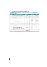
Mode/alarm monitoring word (a 06)
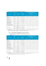
The following table shows the definition of each bit in the mode/alarm monitoring word (a 06).
Bites
Mode/Alarm Bit Description
Read/write
Bit = 0
Bit = 1
0
Manual mode display
Reading
–
Manual
1
Automatic mode display
Reading
–
Automatic
2
Cascade mode display
Reading
–
Cascade
3
LOW-LOW alarm of PV input
Reading
OFF
On
4
LOW alarm of the PV input
Reading
OFF
On
5
PV-input HIGH alarm
Reading
OFF
On
6
PV-input HIGH-HIGH alarm
Reading
OFF
On
7
PV-input deviation alarm (YELLOW)
Reading
OFF
On
8
PV input deviation alarm (RED)
Reading
OFF
On
9
Change rate alarm of PV input
Reading
OFF
On
10
Alarm value setting error
Reading
–
Error
11
PID control operation value overflow/
underflow
Reading
–
Error
12
Under auto tuning
Reading
OFF
On
13
Auto-tuning air
Reading
–
Error
14-15
Reserved
–
–
–
5-2-7
Lamp/soak table flag (a33)
The following table shows the definition of each bit of the lamp/soak table flag word (a33).
Bites
Description of Lamp/Soak Flag Bits
Read/write
Bit = 0
Bit = 1
0
Lamp/soak control start
Writing
–
0
⇒
1:Start
1
Retention of lamp/soak step
Writing
–
0
⇒
1:Retaining
2
Unhold lamp/soak step
Writing
–
0
⇒
1:Resuming
3
Forced Next Step Transfer of Lamp/Soak
Writing
–
0
⇒
1:Transition
4
End of lamp/soak operation
Reading
–
Completion
5
PV value error during lamp/soak
(PV>SP)
Reading
OFF
On
6
Lamp/soak Current Step Retention Status
Reading
OFF
On
7
Contract
Reading
–
–
8-15
8-15 bits to show the current step
Reading
Bytes (hexadecimal)
8 to 15 bits are stored as one byte and the step of the lamp/soak currently running is stored. This byte has the values 1, 2, 3, 4, 5,
6, 7, 8, 9, A, B, C, D, E, F, and 10 representing steps 1-16, respectively. If byte = 0, the lamp/soak table is not used.
Summary of Contents for Kostac SJ-Ether Series
Page 1: ...English version of the KOSTAC SJ Ether series user s manual SJ ETHER USER M...
Page 12: ......
Page 13: ...1...
Page 14: ......
Page 88: ......
Page 89: ......
Page 113: ...3 24 Note Refer to 6 3 3 Module Assembly for connections and locks between modules...
Page 153: ......
Page 156: ...flashing OFF Not sent H W RX Green flashing Receiving H W OFF Not received H W...
Page 161: ...4 8...
Page 221: ......
Page 310: ...Chapter 7 Maintenance...
Page 311: ......

