5-3-3
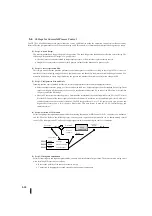
Determining the optimal sample rate (a07)
(1)
Set the process to open loop. (Control does not need to be set yet). Set the CPU to RUN mode. (if already set, set the
control to manual mode) Set the control output value manually. Thus, PV is stable and in the middle of the safety range.
(2)
If there is a minor disturbance in the process, allow a little time. Then, change the control value by 10% steps.
(3)
Record the rise or fall time of the PV (time between 10% and 90% points).
(4)
Divide the recorded rise or fall time into 10 parts. This is the initial sample rate that can be used to start adjusting PID
control.
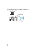
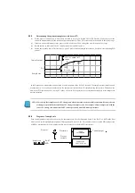
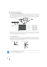
In the figure above, assume that the measured rise time response of the PV is 25 seconds. The sample rate indicated from this
measurement is 2.5 seconds. In the illustration, the sample rate time line shows 10 samples during the rise time. These show the
number of PID operations with varying PV values. Of course, PID operations are performed continuously at the sample rate
during operation.
NOTE: Excessively fast sample rate is a PV change rate alarm that reduces the available resolution. Because the rate
of change is specified in the condition of PV change in sample cycles. For example, a 50 ms sample rate with the
lowest PV change rate means that 20 PV counts per second and 1200 counts per minute.
5-3-4
Program of sample rate
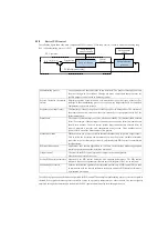
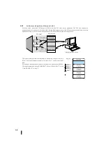
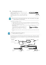
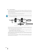
Each control parameter table has a data area for the sample rate. See the illustration below. Area R+07 is a BCD value from
00.05 to 99.99 (with implicit decimal points). This represents 50 ms to 99.99s. This number can be set on the PID setting screen
of KPP or written directly to the register in other ways. It must be set before PID control runs.
PV
10%
90
%
制御出力
サンプル
レート
出力フルレンジの
10
%
立ち上がり時間
V
+
–
X X
X X
BCD
サンプルレート:
R
+
07
セットポイント
偏差
ループ演算
制御出力
プロセス変数
サンプルレート:
00.05
~
99.99
秒
10% of output full
range
Rise time
Control output
Sample rate
Set point
Control output
Loop
calculation
Sample rate :
00.05~99.99 sec
Process
variable
Deviation
Sample rate
Summary of Contents for Kostac SJ-Ether Series
Page 1: ...English version of the KOSTAC SJ Ether series user s manual SJ ETHER USER M...
Page 12: ......
Page 13: ...1...
Page 14: ......
Page 88: ......
Page 89: ......
Page 113: ...3 24 Note Refer to 6 3 3 Module Assembly for connections and locks between modules...
Page 153: ......
Page 156: ...flashing OFF Not sent H W RX Green flashing Receiving H W OFF Not received H W...
Page 161: ...4 8...
Page 221: ......
Page 310: ...Chapter 7 Maintenance...
Page 311: ......

