5-18
5-4
10 Steps for Successful Process Control
The CPU has a sophisticated process control function. It may be difficult to debug the automatic control system. Because many
factors affect the symptoms that occur. When constructing new PID controls, it is recommended that the following steps be taken.
(1)
Step 1: Know a Recipe
The most important knowledge is how to make a product. This knowledge is the foundation for effective control design. The
following is important for the "recipe" of a good process.
Check all process variables related to temperature, pressure, or flow rate that require accurate control.
Design the set point values required for each process variable for the duration of a process cycle.
(2)
Step 2: Control Operation Plan
This simply means that the machine performs control under process variables according to the set point. This is due to a
number of factors, including energy efficiency, equipment costs, and the ability to adjust the machine during production. You
must also decide how to create set points during the process and whether the machine operator can change the SP.
(3)
Step 3: Configuration Size and Scale
Assuming that the control method is effective, select the appropriate actuator and the appropriate sensor.
Select an actuator (heater, pump, etc.) that matches the load size. Actuators larger than the standard have a significant
impact on the post-SP change process. However, a small actuator delays the PV or causes the SP to flow or destabilize
the process after the SP change.
Select a PV sensor that matches the process. Determine the resolution of the control required for the PV (to be 2
℃
or less).
Provide PID control with a sensor input value at least five times its resolution (at the smallest digit bit level). However,
sensitive sensors can cause control vibrations. The SJ-Ether provides a 12-bit, 15-bit, positive only sign, positive and
negative data format, and a 16-bit positive data format. This data format is used for SP, PV, control output, and
cumulative total.
(4)
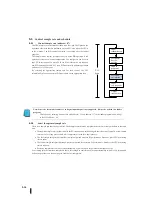
Step 4: Selection of I/O module
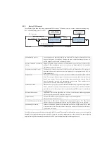
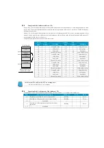
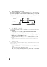
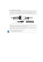
Select the appropriate input/output module after determining the number of PID controls, the PV variables to be measured,
and the SP value. Refer to the following figure. In many cases, input and output modules can be shared among several
controls. The example sends PV and control output signals to two controls using the same set of modules.
(5)
Step 5: Wiring and Installation
Select all control parts and input/output modules, and wire and install them after purchase. The most common wiring errors
when installing PID control are as follows.
Reverse the polarity of the sensor or actuator wiring.
Connection of inappropriate ground signals between control components.
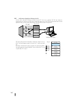
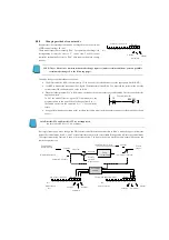
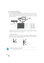
+
–
R2002
XXXX
R2003
XXXX
R2005
XXXX
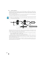
セットポイント:
R
+
02
偏差
ループ演算
制御出力:
R
+
05
プロセス変数:
R
+
03
ループテーブル
セットポイント
プロセス変数
制御出力
Set point
Deviation
Loop
calculation
Control
output
Process
variable
Loop table
Set point
Process variable
Control output
Summary of Contents for Kostac SJ-Ether Series
Page 1: ...English version of the KOSTAC SJ Ether series user s manual SJ ETHER USER M...
Page 12: ......
Page 13: ...1...
Page 14: ......
Page 88: ......
Page 89: ......
Page 113: ...3 24 Note Refer to 6 3 3 Module Assembly for connections and locks between modules...
Page 153: ......
Page 156: ...flashing OFF Not sent H W RX Green flashing Receiving H W OFF Not received H W...
Page 161: ...4 8...
Page 221: ......
Page 310: ...Chapter 7 Maintenance...
Page 311: ......


