5-20
5-5
Basic control operation
5-5-1
Data position
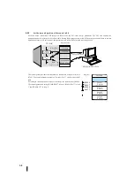
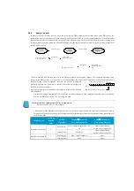
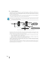
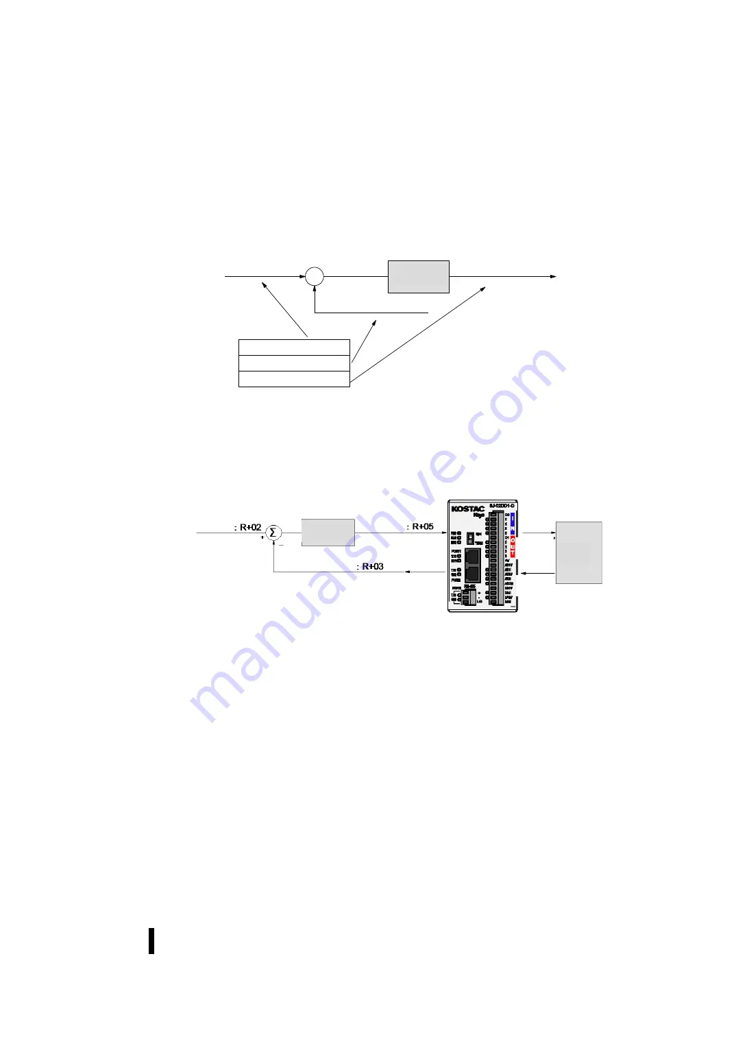
Each PID control depends on how the control table is used and the data values. The following figure shows an example of the
control table area corresponding to the three main loop variables: SP, PV, and control output. The following example begins with
R2000. The SP, PV, and control output are located at the indicated address.
5-5-2
Data source
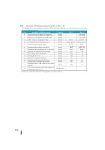
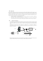
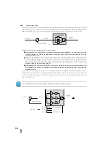
The SP, PV, and control output data must be interfaced to the device. In the figure below, the source and distribution are shown
for each PID control variable. The control output and process variable values move through the analog input and analog output
modules to interface with the process itself.
Several circuits in the ladder are required to copy data from the analog module to the control table, or vice versa.
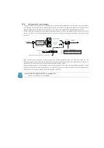
As shown above, the set point has several sources. Depending on the PID control mode, many applications use more than one
source at different times. In addition, the PID control operation and programming method determines how set points are
created.
When using the built-in lamp/soak generator or cascading PID control, the PID controller automatically writes set point data to
the position of R+02.
If you wish to write a set point from another source, you must write the set point in the ladder program to the control table R+02.
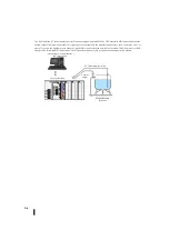
Each of the three main control parameters can have only one source or distribution within a given time. When developing an
application, create a control wiring diagram showing the source of the data to avoid errors.
+
–
R2002
XXXX
R2003
XXXX
R2005
XXXX
セットポイント:
R
+
02
偏差
ループ演算
制御出力:
R
+
05
プロセス変数:
R
+
03
ループテーブル
セットポイント
プロセス変数
制御出力
Set point
Deviation
Loop
calculation
Control
output
Process
variable
Loop table
Set point
Process variable
Control output
Set point
Loop
calculation
Control
output
Process
variable
Set point setting way
Operate input
Lamp/Soak generator
Ladder program
Another loop output (cascade)
Analog
output
Analog
input
Error
term
Summary of Contents for Kostac SJ-Ether Series
Page 1: ...English version of the KOSTAC SJ Ether series user s manual SJ ETHER USER M...
Page 12: ......
Page 13: ...1...
Page 14: ......
Page 88: ......
Page 89: ......
Page 113: ...3 24 Note Refer to 6 3 3 Module Assembly for connections and locks between modules...
Page 153: ......
Page 156: ...flashing OFF Not sent H W RX Green flashing Receiving H W OFF Not received H W...
Page 161: ...4 8...
Page 221: ......
Page 310: ...Chapter 7 Maintenance...
Page 311: ......

