5-24
5-5-6
PID mode control using the operator panel
Since manual, automatic, and cascade modes are the most basic and important PID controls, the operator panel may require
"hard wiring" for the mode control switch. Most applications require only manual and automatic selection (the cascade is used
in more sophisticated applications). Remember that the control mode is the bit requesting a mode change, and the actual control
mode is stored elsewhere.
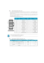
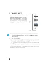
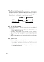
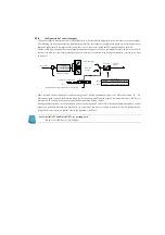
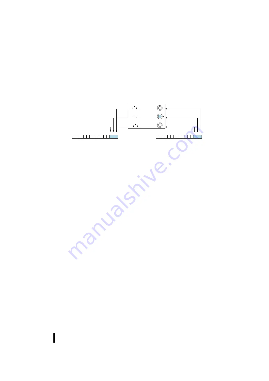
The following figure shows an example of using the pushbutton on the operator panel to request a change in PID mode. The
mode display on the panel is not connected to the switch but interfaces to the corresponding data location.
5-5-7
Effect of PLC mode by control mode
If PID control selects options that link to PLC mode, PLC mode (STOP, RUN) interacts with PID control. These interactions
are summarized below.
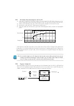
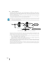
When PLC is in STOP mode, all PID controls are in manual mode and not all PID controls are performed.
Note that the output module (including analogue output) is OFF when the PLC is in STOP mode. Therefore, when PLC
is in STOP mode, actual manual control is not performed.
The CPU allows you to change the control mode when the PLC is in RUN mode. The CPU records the mode of all 16
loops as the required mode of operation. If power failure and power recovery occur during RUN mode, the CPU returns
all control to the previous mode (manual, automatic, or cascade).
When switching from STOP to RUN mode, the CPU forces the control to return to the previous RUN mode of
operation.
Only when the PLC is in STOP mode, can make new controls be applied or set. The new control starts automatically in
manual mode.
5-5-8
Control mode override
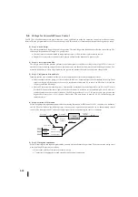
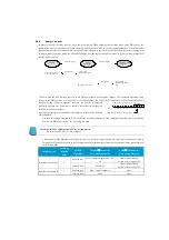
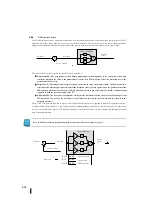
Typically, the control mode is determined by requesting bit 0, 1, and 2 of R+00. However, there are several factors that do not
change to the requested mode.
・
PID control linked to PLC mode is when PLC is in STOP mode.
・
When the measure loop is in cascade mode, the combination of the cascade in PID control cannot be controlled
manually and automatically. Otherwise, the control mode is automatically changed because the PID control operates
safely.
・
PID control, including error factors, automatically becomes manual.
・
If, in multiple cascade modes, an error occurs in the minor loop of the combination of the PID control, the measure
loop is automatically changed to manual mode.
0
1
3
4
5
6
7
8
9
10
11
12
13
14
15
2
Bit
0
1
3
4
5
6
7
8
9
10
11
12
13
14
15
2
Bit
オペレータのパネル
モード要求
PID
モード
1
設定ワード:
R
+
00
ビット
手動
自動
カスケード
ループモードとアラームステータス:
R
+
06
モード監視
ビット
PID mode 1 setting word
Loop mode and alarm status
Mode request
Manual
Automatic
Cascade
Mode monitoring
Bit
Bit
Operator’s panel
Summary of Contents for Kostac SJ-Ether Series
Page 1: ...English version of the KOSTAC SJ Ether series user s manual SJ ETHER USER M...
Page 12: ......
Page 13: ...1...
Page 14: ......
Page 88: ......
Page 89: ......
Page 113: ...3 24 Note Refer to 6 3 3 Module Assembly for connections and locks between modules...
Page 153: ......
Page 156: ...flashing OFF Not sent H W RX Green flashing Receiving H W OFF Not received H W...
Page 161: ...4 8...
Page 221: ......
Page 310: ...Chapter 7 Maintenance...
Page 311: ......

