5-5-9
Bumper transfer
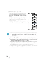
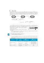
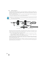
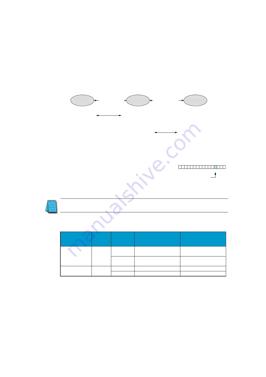
In process controls, the term "transfer" has a specific meaning. When changing the operation mode of the PID control, the
transmission occurs as shown below. When changing the PID control mode, set several control parameters. When the control
changes from manual to automatic mode, the control output changes to the control controller. When the control changes from
automatic mode to cascade mode, the SP control changes from the source in automatic mode to the output from another PID
control (upper control).
The basic problem with control transfer is to use different values when the mode changes. This causes an undesirable step
change in the PID operation or a "collision" in the control output. As a result, PID control fails. When the control mode is
changed by the "bumpless transfer" function, the transfer is smoothly
performed because one parameter is forcibly equivalent to another (no
collision in the control output).
Two types of features are available for the bumpless transfer of the SJ Ether
PID controllers.
・
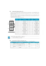
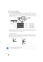
Use the PID setting dialog box for KPP to select the no-collision bumpless I and bumpless II transfer types. Alternatively,
bits 3 of the PID mode setting 1 R + 00 setting are used.
Note: DirectSOFT4 and DirectSOFT5 are not supported.
Be sure to use KPP Ver1. 5.0.0 or higher.
・
Characteristics of the bumpless I and II transfer types are shown in the figure below. Note which of the position or velocity
forms of the PID equation is used in the PID algorithm. Note that bumpless I must be used when using the speed format of
the PID algorithm.
Switching type
Switching
selection
Bites
For PID
Algorithm
Manual
⇒
Auto mode
Forwarding behavior
Auto
⇒
Vertical mode
Forwarding behavior
Bumpless switching I
0
Position type
Bias = control output set, SP = PV
set
Upper control output=
Set lower-level control PV
Velocity form
Set SP=PV
Upper control output=
Set lower-level control PV
Bumpless Switching II
1
Position type
Bias = control output set
None
Velocity form
None
None
0
1
3
4
5
6
7
8
9
10
11
12
13
14
15
2
Bit
バンプレス切替えⅠ
/
Ⅱ選択
ビット
PID
モード
1
設定ワード:
R
+
00
オペレータによる
ループ出力生成
モード変更
モード変更
自動
カスケード
転送
PID
によるループ
出力演算
ローカルで
生成された
SP
手動
転送
上位ループにより
リモートで
生成された
SP
Manual
Automatic
Cascade
Mode switching
Mode switching
Generation of loop
output by operators
Loop output
calculation by PID
SP generated in local
Transmission
SP generated in
remote by the upper
loop
PID mode 1 setting word
Bit
Bumpless switching
Ⅰ
/
Ⅱ
selection
Transmission
Summary of Contents for Kostac SJ-Ether Series
Page 1: ...English version of the KOSTAC SJ Ether series user s manual SJ ETHER USER M...
Page 12: ......
Page 13: ...1...
Page 14: ......
Page 88: ......
Page 89: ......
Page 113: ...3 24 Note Refer to 6 3 3 Module Assembly for connections and locks between modules...
Page 153: ......
Page 156: ...flashing OFF Not sent H W RX Green flashing Receiving H W OFF Not received H W...
Page 161: ...4 8...
Page 221: ......
Page 310: ...Chapter 7 Maintenance...
Page 311: ......

