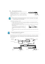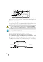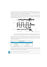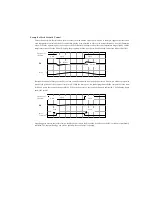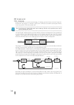
figure. Assuming that the PV signal is turned off, the PV value will be zero. During a significant PID control failure, the reset
windup may be worse. Note that the bias value is accumulated until it reaches its upper limit while the PV signal is turned off.
When the PV signal returns, the bias value saturates (wind-up) and returns to the normal value over a long period of time. As a
result, it takes a long time for the control output to recover. The output level will produce an incorrect output until it recovers,
causing a problem.
In the example shown in the figure, when the second PV signal is turned off, the bias lock function is enabled. Fix the bias value
when the control output moves outside the limit. Many reset windups are thus avoided. The return time of the output is much
less.
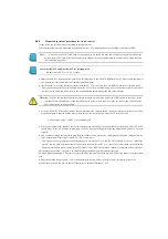
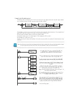
In most applications, the bias locking feature is used with PID control, as
described above. Use the PID setting dialog for KPP to enable this feature or
set bit 10 of PID mode setting 1 to the right.
Note :
The bias fixation function stops the bias value when the control output reaches the output range. If the set range of the
control output is set to a value that exceeds the output limit (i.e., 4046 or more when the positive sign is only /12-bit
control 0-4095), the bias fixation function will not work.
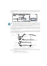
Feed forwards described later in this chapter allow you to write bias values directly from the ladder circuit. However, the bias
condition does not compete with the bias locking feature because it is very rare to write the bias term with the feed forward
during operation.
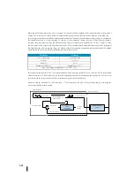
Note: DirectSOFT4 and DirectSOFT5 are not supported.
Be sure to use KPP Ver1. 5.0.0 or higher.
0
1
3
4
5
6
7
8
9
10
11
12
13
14
15
2
Bit
PID
モード
1
設定ワード:
R
+
00
バイアス固定の選択
ビット
0
PV
バイアス
出力
PV
損失
PV
損失
リセットワインドアップ
バイアス固定を有効
復帰時間
復帰時間
PV loss
PV loss
Reset windup
Valid fixed bias
Bias
Output
Return time
Return time
PID mode 1 setting word
Selection of fixed bias
Bit
Summary of Contents for Kostac SJ-Ether Series
Page 1: ...English version of the KOSTAC SJ Ether series user s manual SJ ETHER USER M...
Page 12: ......
Page 13: ...1...
Page 14: ......
Page 88: ......
Page 89: ......
Page 113: ...3 24 Note Refer to 6 3 3 Module Assembly for connections and locks between modules...
Page 153: ......
Page 156: ...flashing OFF Not sent H W RX Green flashing Receiving H W OFF Not received H W...
Page 161: ...4 8...
Page 221: ......
Page 310: ...Chapter 7 Maintenance...
Page 311: ......

