5-9-2
Manual adjustment procedure for closed control
Use the following checklist before switching to automatic mode.
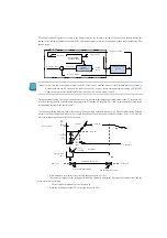
The control parameters are monitored by peripheral devices. It is recommended to use the PID view feature of KPP.
Note :
You can use the PID Trend View Settings menu to set the SP/PV area and the bias/control output area on the
horizontal axis. The Auto Scale function otherwise changes the process parameters to a vertical scale, which confuses
the control tuning process.
Note: DirectSOFT4 and DirectSOFT5 are not supported.
Be sure to use KPP Ver1. 5.0.0 or higher.
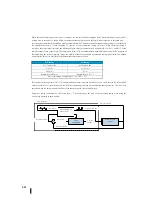
Adjust the gain to 10 for proportional gain, 9999 for integral gain, and 0000 for differential gain. This overrides the integral
and differential terms and makes them small proportional gains.
Check the bias value of the control parameter table (R+04). If it is not zero, then use KPP to write zero to the bias value.
Now you can change PID control to automatic mode. Check the mode monitoring bit to confirm the current mode. If PID
control is not in automatic mode, refer to the troubleshooting information at the end of this chapter.
Warning
If the PV and control output values vibrate, immediately reduce the gain value. If PID control is not stable, return
to manual mode and manually set the control output to a safe value. Always place the emergency stop switch near the
PID control tuning to stop operation.
At this point, SP=PV will be generated by the bumpless function. Increase the SP slightly so that the deviation occurs. If the
proportional gain is enabled and the bias value is set to 0, the control output value can be easily checked.
Control output value = (SP-PV) × proportional gain
If the control output value changes, the control should obtain more energy from the actuator, heater, or other device. The PV
should move in the SP direction immediately. If the PV does not change, increase the proportional gain until it moves
slightly.
Add a small amount of the integration gain. Remember that a large number is a small integral gain and a small number is a
large integral gain! If this step is closed, PV = SP or very close.
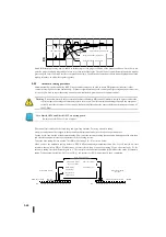
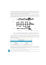
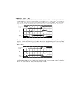
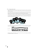
Until this point, only proportional and integrated gains were used. Next, when the SP is changed by 10% to "impact the
process" and the gain is adjusted, there is an optimal response for the PV as a result. This is illustrated in the following
figure. Adjust the gain while looking at the PID Trend view of KPP. The fastest PV response is obtained without vibration.
Wide proportional band - The gain is so small that the proportional gain is gradually increased.
Narrow proportional band - The gain is very large. Reduce the integration gain first and if necessary, reduce the proportional
gain.
Proportional band is appropriate - This is the optimal gain setting. This is the best response to slightly increase the
proportional gain, and you can see that PID control has a small oscillation of 1 or 2.
Summary of Contents for Kostac SJ-Ether Series
Page 1: ...English version of the KOSTAC SJ Ether series user s manual SJ ETHER USER M...
Page 12: ......
Page 13: ...1...
Page 14: ......
Page 88: ......
Page 89: ......
Page 113: ...3 24 Note Refer to 6 3 3 Module Assembly for connections and locks between modules...
Page 153: ......
Page 156: ...flashing OFF Not sent H W RX Green flashing Receiving H W OFF Not received H W...
Page 161: ...4 8...
Page 221: ......
Page 310: ...Chapter 7 Maintenance...
Page 311: ......

