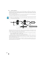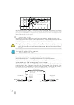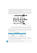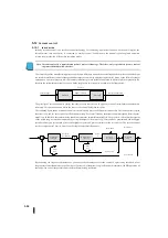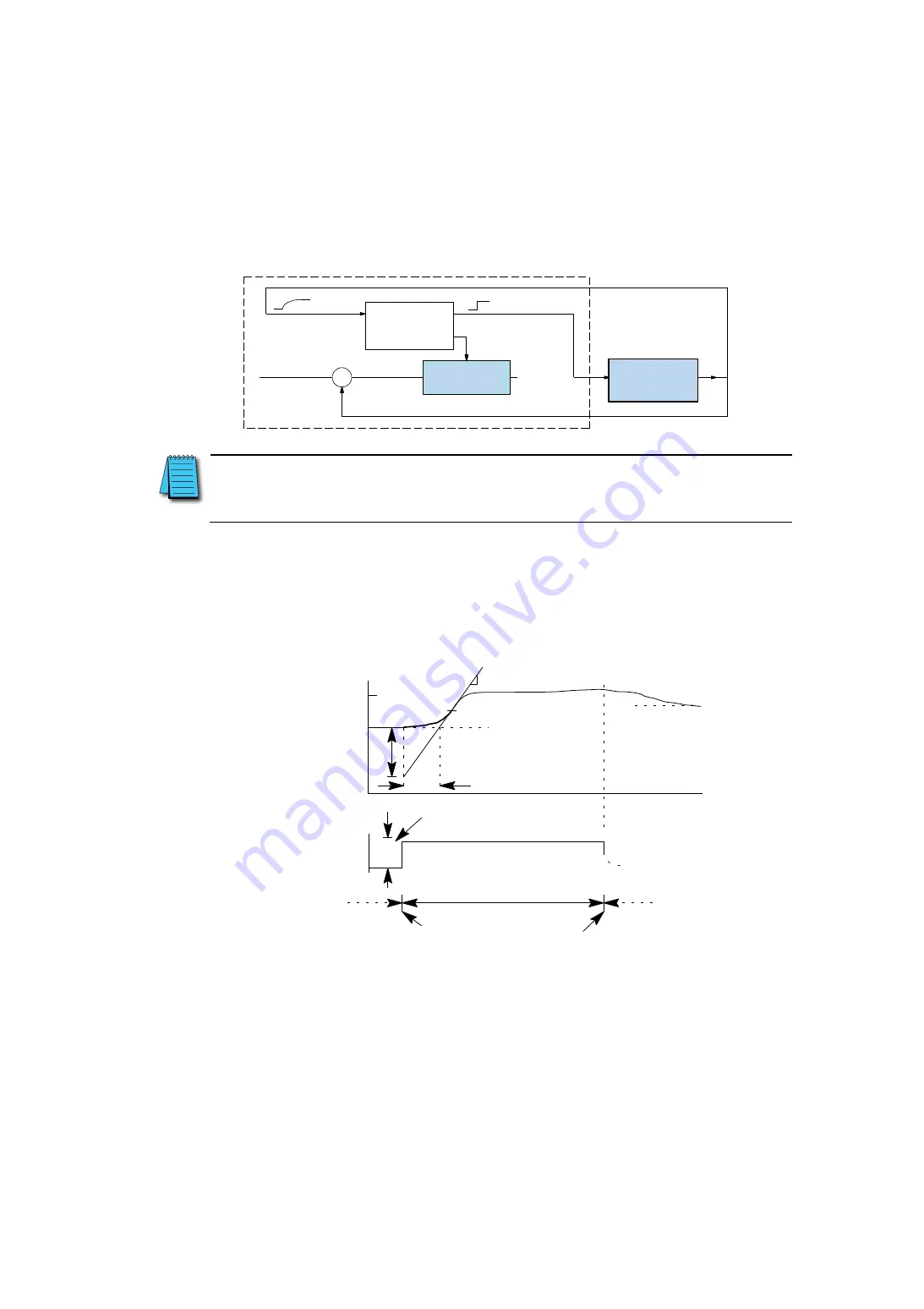
The control controller operates as shown in the figure below during automatic tuning of the open loop. Before starting the
tuning, set the control manual mode so that the PV and control output values are in the middle of their range (point away from
the end point).
Note :
In this case, the control is not closed, so the SP value is not a problem. However, the firmware must be located at a
distance between the SP value and the count value of 205 or more before starting automatic tuning. (SP-PV
≧
205
Count for positive action control and PV-SP
≦
205 Count for reverse action control)
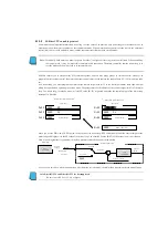
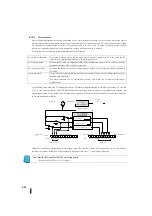
During automatic tuning, the control controller causes a step change to the output and simply observes the PV response. The
automatic tuning function calculates gain and sample time from the PV response. The result is automatically stored in the
corresponding register in the control table.
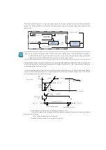
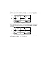
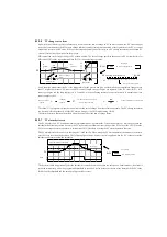
The following timing diagram shows the results of the open-loop automatic tuning cycle. The automatic tuning function
controls the control output and causes a 10% length step change. When the control controller changes PV by 2% or less, the
next step in the output is raised to 20% of the span.
* When automatic adjustment starts, the step change output Δm = 10%.
* The controller output reaches the upper limit during automatic adjustment. Automatic adjustment stops and the
alarm status bit is activated.
The automatic adjustment error bit is turned on.
* When the PV changes below 2%, the output changes to 20%.
+
–
PLC
システム
応答
開 ル ー プ に よ る
自 動 チ ュ ー ニ ン
グ
ループ演算
製造プロセス
ステップ機能
セットポイント値
偏差
制御出力
プロセス変数
プロセス変数
SP
PV
(%)
Lr
(sec.)
LrRr
(%)
プロセス波
接線
Rr
=傾度
基線
時間(秒)
ステップ変更
△
m=10%
出力値
(%)
PID
サイクル
自動チューニングサイクル
自動チューニング開始
自動チューニング終了
(秒)
PID
サイクル
PLC System
Loop
calculation
Control
output
Set point value
Process variable
Deviation
Process variable
Response
Step function
Manufacturing
process
Auto tuning
by open loop
Process wave
Tangent
Gradient
Base line
(Sec)
Time (Sec)
Step
change
PID cycle
Automatic tuning cycle
Start of automatic tuning
End of automatic tuning
PID cycle
Output value
Summary of Contents for Kostac SJ-Ether Series
Page 1: ...English version of the KOSTAC SJ Ether series user s manual SJ ETHER USER M...
Page 12: ......
Page 13: ...1...
Page 14: ......
Page 88: ......
Page 89: ......
Page 113: ...3 24 Note Refer to 6 3 3 Module Assembly for connections and locks between modules...
Page 153: ......
Page 156: ...flashing OFF Not sent H W RX Green flashing Receiving H W OFF Not received H W...
Page 161: ...4 8...
Page 221: ......
Page 310: ...Chapter 7 Maintenance...
Page 311: ......

